Use the Elevation mark settings dialog to define a new style or modify an existing style of description of elevation marks; the elevation mark consists of a symbol and a coordinate.
The dialog displays after you click New or Modify in the Styles of descriptions dialog when the Elevation marks category is selected.
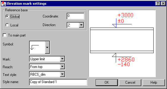
Define parameters :
- Style name - use this edit field to specify a name for the style
- Under Reference base, choose the coordinate system (global coordinate system of a model or local coordinate system of an element) that is the basis for defining elevation reference (coordinate) and direction.
- If To main part is selected for assemblies and groups, limits are determined for a main part of the group and not for a group as a whole.
- For Symbol, select an elevation symbol provided with the software.
- For Mark, select a part of the element edge (upper limit, lower limit, or both) on which an elevation mark is to be generated. Symbols are generated automatically at the most distant point along the selected direction.
- For Reach, define a point of connection between a symbol and an edge of a dimensioned element (from top, from bottom, or aligned).
- Text style - select a font to be applied in descriptions.
Symbols are located near edges of a dimensioned element (inside dimension lines).