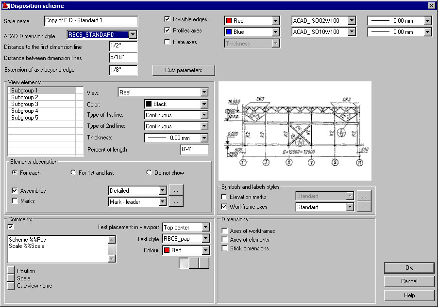
Use the Disposition scheme dialog to define a new style or to modify an existing dimensioning style for the disposition scheme (a group of elements constituting a structure model).
This dialog opens after you click New or Modify in the Dimensioning styles dialog (the scheme has to be selected as a style category).
- ACAD Dimension style - select an AutoCAD® dimensioning style that will be applied in the dimensioning style currently selected. The list contains all the dimensioning styles defined in a DWG format file
- Distance to the first dimension line - specify the distance between the edge of a dimensioned part and the first dimension line generated automatically
- Distance between dimension lines - specify the distance between successive dimension lines
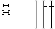
- Extension of axis beyond edge - specify the length of lines that extend outside the element edges on both sides of the element
- Invisible edges - if this is not selected, invisible edges of an element are hidden in a final drawing. If this is selected, invisible edges are displayed in a drawing (specify their line color, line type, and line thickness parameters at the right of the option)
- Profile axes - if this is not selected, profile axes are hidden in a final drawing. If this is selected, profile axes are displayed in a drawing (specify their line color, line type, and line thickness parameters at the right of the option). Profile axes are displayed in all projections; in final drawings, axes are extended by 5 mm outside the edge of a dimensioned object
Click the Cuts parameters button in the upper part of the dialog to open the Cut parameters dialog where you can specify parameters of hatching the cut and parameters for designating the cut in disposition schemes.
- Real - a real view of each element
- Rectangular box - a view of each element is represented as a rectangular contour
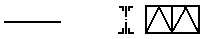
- Line - a view of each element is represented as a single line
- Double line
-
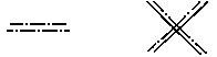
- Column line
-
- Truss scheme
-
- Rectangular box - group - for all elements of a group (also for elements in subgroups), the view is represented as a rectangular contour circumscribed on elements of the group
- Line - group - represented as the largest central (single) line of the rectangular contour circumscribed on elements of the group
- Double line - group - represented as the largest central (double) line of the rectangular contour circumscribed on elements of the group
- Column line - group - represented as the largest central line (column line) of the rectangular contour circumscribed on elements of the group
- For each element of a scheme
- Only for the first and last elements
- Do not show
Moreover, you can select styles for assemblies and marks.
You can specify a value of shortening (in percent) of an element length.
- Stick dimensions - distances of elements from axes in a scheme (if an element lies on the axis, then a 0 dimension is not shown)
- Level marks - level symbols, separately for each subgroup of the scheme
- Axial dimensions - dimensions from axis to axis of elements of a scheme
- Level dimensions - additional dimension lines of elements (on the side of a scheme, near the level marks); a dimension chain from the lowest to the highest level in the scheme is created.
If Comments is selected, a title (name) is added to the views of a dimensioned object. The title may be text (comprising one or several lines) containing variables or any user-defined character string. Below the text field are variables that you can add to the defined comment at the cursor position. The variable text is displayed with the comment in the edit field.
Available comment variables:
%%Pos - if this is selected, description of a position is added to the text
%%Scale - if this is selected, a scale (for example, 1:20) is added to the text
%%Vname - if this is selected, an automatic name of a view or section is added to the text
- Text placement in viewport
- T ext style
- Alignment (align right, align left, center)
- Under Symbol and layer styles, select styles for the following descriptions and symbols (designations) presented in final drawings:
- Elevation marks
- Workframe axes