Use this option to define grates.
To begin defining a grate, open the Grates dialog from:
- Menu: Steel > Grates
- Ribbon: ASD - Model > Elements > Grates
- Toolbar: General > Grates

- Command line: RBCS_GRATE.
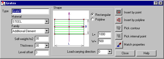
The Grates dialog has 3 main parts:
- On the left, you can specify basic information for a defined grate:
- Type - specify a name of the defined grate
- Material - select a material type assigned to the defined grate
- Family - select a family (group) of grates to which the defined grate will be assigned
- Self-weight - based on this value the program calculates a grate weight
- Thickness - select a value of grate thickness or enter a value into the edit field
- Level offset - a value of the distance between the grate insertion point and the bottom left corner of the grate; an offset equals 0, if the bottom left corner of the grate coincides with the grate insertion point
- In the middle is a graphical field that displays the defined grate, and where you can specify a grate shape:
- Rectangular - when this is selected, you can define side dimensions W and L
- Polyline - any shape defined by means of a polyline
You can define a load-carrying direction for the grate (an angle in the XY plane); the direction is displayed in the model layout and drawings using the symbol
 . The longer axis of the symbol is parallel to the load-carrying direction of the grate. The symbol of the load-carrying direction is displayed (in the same color and the same style as the grate edges) only in a top view and a 3D view of the grate in the plane parallel to the grate plane. The grate with its basic elements is illustrated below:
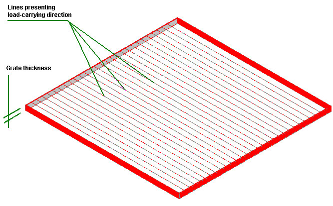
- Use the icon on the right to define the grate insertion:
 - point (not available for a shape defined by polyline)
  - polyline
  - Pick contour - available for user-defined grates, but not available for rectangular grates
  - Pick internal point - available for user-defined grates, but not available for rectangular grates
  Match properties - used to adopt parameters from a defined grate
When the Grates dialog displays, it displays the grate parameters most recently defined.