The example below presents the definition of a section of a steel flat bar that may be used in definition of a structure model. To define a user-defined section (bar section):
- Applying AutoCAD® options:
- Draw a rectangle (Draw menu > Rectangle) with the dimensions 590x4050 (see the drawing below).
- Select a region (Draw menu > Region) and indicate the rectangle drawn.
- Applying Autodesk AutoCAD Structural Detailing - Steel options:
- Click the User sections
 .
. - Specify the defined region (rectangle).
- Select to save the section in the current project (the Locally option in the command line). Note: If InDatabase option is selected in the command line, use the Saving section to database dialog to save a profile to a database:
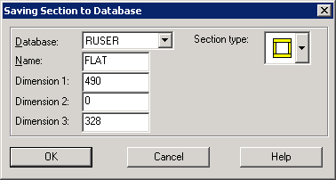
- Specify a name, a maximum of 4 letters (digits are not allowed).
- Define dimensions of the profile (real numbers defining information about the profile)
- If 1 dimension is given, specify Dimension 1
- If 2 dimensions are given, specify Dimension 1 and Dimension 3
- Specify a section name (4 letters and designations describing profile dimensions, such as FLAT 590x4050).
- Define a profile shape code.
- Click the User sections
Note: Section codes are adopted according to designations used in Robot; code descriptions are provided in Robot help.
Thus-defined section of a profile will be added to the list of available profiles (in the Profile dialog, a part of which is shown in the drawing below). The section will be available only in the current project.
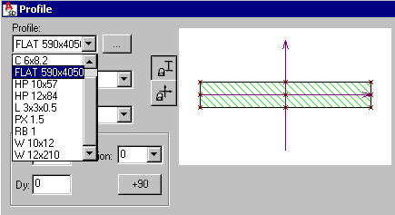
See also: List of profile shape codes