The link between Autodesk Robot Structural Analysis (a calculation program) and Autodesk AutoCAD Structural Detailing (used to create drawings) has been designed in order to enable you to:
- Perform calculations of a defined CAD 3D model using Autodesk Robot Structural Analysis at any work stage. Calculations may be performed both for a whole structure and for a selected structure part.
- Apply a calculation model created in Autodesk Robot Structural Analysis as the basis for creation of a detailed CAD model and documentation of a designed structure.
- Autodesk Robot Structural AnalysisPerform full synchronization (from Autodesk Robot Structural Analysis to Autodesk AutoCAD Structural Detailing and vice versa) of changes made in a structure calculation model as well as in its CAD model.
Updating the CAD file and the file containing the structure calculation model is carried out in the Link Wizard dialog shown below. To open the Link wizard dialog from:
- Menu: Steel > Analysis Interface - Robot
- Ribbon: ASD - Model > Tools > Analysis Interface - Robot
- Toolbar: General > Analysis Interface

- Command line: RBCS_R2R.
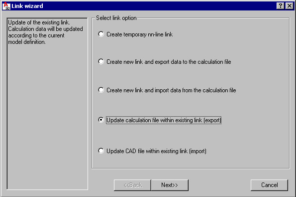
To begin updating data for a selected Autodesk Robot Structural Analysis - Autodesk AutoCAD Structural Detailing connection defined in the current CAD file, choose an available operation:
- To create a new link (permanent or temporary), select one of the first three options.
- To update an existing link, select one of the last two options (update of a structure calculation model based on changes made in Autodesk AutoCAD Structural Detailing or vice versa).
The left pane of the Link wizard dialog displays a short description of the option selected on the right.
After you click Next, the Link wizard dialog changes as shown below, allowing you to:
- Assign a name of the defined link or select a name of the existing link
- Create or select a file with an RTD extension (a file of the Autodesk Robot Structural Analysis calculation program) in which calculation results will be saved
- Select objects that will be considered while creating a link.
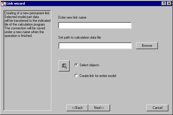
To create a new link:
- For Enter new link name, specify a link name. This field is available only when you're creating a permanent link. The link is saved under a specified name in the current DWG file. Because the name identifies links, it must be unique in a given file.
- For Set path to calculation data file, specify a calculation file with an RTD extension (an Autodesk Robot Structural Analysis file) to which calculation results for the created link will be saved. This field is available only when you're creating a new permanent link. As data is updated, the path is displayed in the field, but is read-only. You can specify a file by clicking Browse, and then using one of the standard Windows dialogs that displays:
- Open dialog - displays when you are importing data from an existing file that contains a calculation model (RTD file).
- Save dialog - displays when you are exporting data to a new file that is being created at this stage.
- The options provided at the bottom of the Link wizard dialog let you select objects that are to be link components (the options are available only when a new link is being created):
- Create link for entire model - select this option in order to use the entire structure
- Select objects - select this option in order to specify individual structure objects. When you use this option, you can click the button that then lets you select objects in the drawing.
To update an existing link:
- For Choose link, select one of the permanent links available in the current DWG file. After a link is selected, it becomes active. The list of all permanent links defined in the current DWG file may be viewed (and configured, if needed) in the additional dialog that opens after you click See list.
- Click Next to display a dialog (shown below) where you can specify parameters of data transfer. The options in this dialog depend on the option (direction of data update) chosen in the first dialog.
- For a new link, the default options are selected.
- For an existing link, the options that are selected are those that were applied for the selected link during the last operation of data update.
You can change any of the options.

To create a link and begin data update based on the options selected in the above dialogs, clickStart data update. The current dialog is closed, and a data update report displays. Data update is an obligatory operation while creating a new link.
This dialog displays the run of the data update process. A progress bar displays at the bottom of the dialog, reporting the progress of the data update operation. Messages related to the data update process display also:
- Date of the update process
- File names (source file and target file)
- Direction of the data update process (from Autodesk AutoCAD Structural Detailing or to Autodesk AutoCAD Structural Detailing)
- Warnings
To save the contents of the data update report in a text file, click Save log file. A text file may be corrected manually by the user.
The OK and Save log file buttons are available only after the data update process is completed.