Specify how curved elements are displayed on the screen and dimensioned.
Single parts:
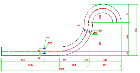
- When Orthogonal is selected, curved parts display as standard objects so that their actual shape is shown and dimensions are generated in the orthogonal system (compare example dimensions generated with the use of this option in the drawing below).
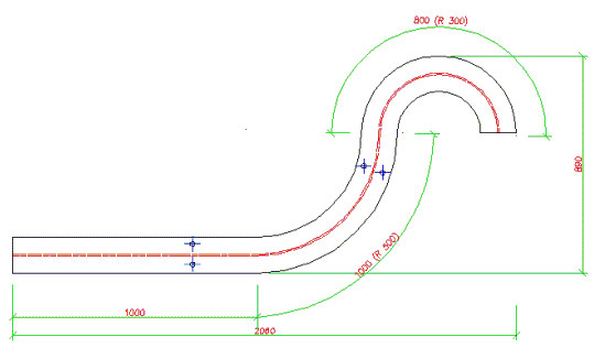
- When Aligned to curve is selected, curved parts display as curved objects so that their actual shape is shown and dimensions are generated in the system adjusted to the profile curvature (compare example dimensions generated with the use of this option in the drawing below). Total dimensions are displayed in the orthogonal system (coordinate system of the curved part), and the remaining dimensions are generated in the longitudinal / transversal system. Longitudinal dimensions are always parallel to the profile axis (dimension values are calculated along the length of arc axis, and a radius value is given in parentheses); transverse dimensions are segments perpendicular to the profile axis and passing through the dimension point.
- When Developed is selected, object dimensions are displayed in the developed form in the orthogonal system. Click Options to open the Developed parts dialog.
Assemblies
- When Orthogonal is selected, assemblies display as standard elements so that their actual shape is shown and dimensions are generated in the orthogonal system.
- When Aligned to curve is selected, assemblies are displayed as curved elements so that their actual shape is shown and dimensions are generated in the system adjusted to the profile curvature. Total dimensions are displayed in the orthogonal system (coordinate system of the curved part), and the remaining dimensions are generated in the longitudinal / transversal system. Longitudinal dimensions are always parallel to the main part axis (dimension values are calculated along the length of arc axis, and a radius value is given in parentheses). Total transverse dimensions are determined by cutting planes (external transverse dimensions are parallel to total transverse dimensions); internal transverse dimensions are segments perpendicular to the profile axis and passing through the dimension point.
Single parts
For the Orthogonal and Aligned to curve options, projections of the actual element shape are obtained, and elements are projected onto planes of the coordinate system of a curved part. The coordinate system of a curved part is a coordinate system used only in drawings, defined as follows:
- For profiles
If a profile includes linear segments, the longest segment is selected and the coordinate system of a curved part coincides with the coordinate system of this segment (as if it were a single simple profile).
If a profile does not contain linear segments, the coordinate system of a curved part may be defined as:
- Method A - the X axis of the coordinate system of a curved part is positioned along the chord of the longest (among all parts) arc segment
- Method B - the X axis of the coordinate system of a curved part is tangent to the chord of the longest (among all parts) arc segment at the beginning point
The method of defining the coordinate system of a curved part is selected in the Dimensioning Style Settings dialog:
- If Align arc profiles to the chord is not selected, the coordinate system is defined using method A.
- If Align arc profiles to the chord is selected, the coordinate system is defined using method B.
In both cases, the Y axis of the coordinate system of a curved part is positioned in the plane of part bending, irrespective of profile rotation.
- For plates
The coordinate system of a curved part is identical with the part UCS.
Assemblies
Assemblies are considered curved if the main part of an assembly is curved. For curved assemblies, projections of the actual element shape are obtained, and elements are projected onto planes of the coordinate system of a curved part (main part of an assembly). The coordinate system of a curved part is defined as for a single part.