点および曲線オブジェクト
参照点は、コンセプト デザイン環境の XYZ 作業スペースで場所を指定する要素です。参照点を線分、スプライン、フォームの設計や印刷のために作成します。ReferencePoint は ReferencePointArray に追加することができ、その後、フォームの作成に使用する CurveByPoints を作成するために使用することができます。
次の例は、CurveByPoints オブジェクトを作成する方法を示します。複数の CurveByPoints オブジェクトからフォームを作成する方法については、次のセクションの「ロフト フォームを作成する」の例を参照してください。
|
コード領域 14-1: 新しい CurveByPoints を作成 |
ReferencePointArray rpa = new ReferencePointArray(); XYZ xyz = document.Application.Create.NewXYZ(0, 0, 0); ReferencePoint rp = document.FamilyCreate.NewReferencePoint(xyz); rpa.Append(rp); xyz = document.Application.Create.NewXYZ(0, 30, 10); rp = document.FamilyCreate.NewReferencePoint(xyz); rpa.Append(rp); xyz = document.Application.Create.NewXYZ(0, 60, 0); rp = document.FamilyCreate.NewReferencePoint(xyz); rpa.Append(rp); xyz = document.Application.Create.NewXYZ(0, 100, 30); rp = document.FamilyCreate.NewReferencePoint(xyz); rpa.Append(rp); xyz = document.Application.Create.NewXYZ(0, 150, 0); rp = document.FamilyCreate.NewReferencePoint(xyz); rpa.Append(rp); CurveByPoints curve = document.FamilyCreate.NewCurveByPoints(rpa); |
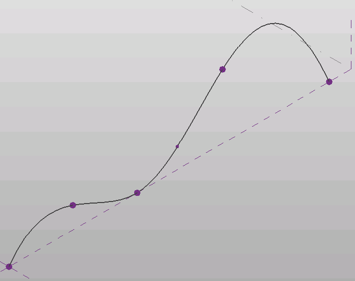
図 54: CurveByPoints 曲線
参照点は、上記の例のように XYZ 座標に基づいて作成するか、参照されるジオメトリが変更される際に点が移動するよう、他のジオメトリを基準にして作成できます。これらの点は PointElementReference クラスのサブクラスを使用して作成されます。次のサブクラスがあります。
- PointOnEdge
- PointOnEdgeEdgeIntersection
- PointOnEdgeFaceIntersection
- PointOnFace
- PointOnPlane
たとえば、前述の例にあるコードの最後の 2 行は CurveByPoints の中間に参照点を作成します。
フォームはモデル線分や参照線を使用して作成できます。モデル線分は、作成中にフォームによって「消費」され、個別のエンティティとして存在しなくなります。一方、参照線はフォームが作成された後も存在し、移動するとフォームが変更されます。API には ReferenceLine クラスがありませんが、ModelCurve.ChangeToReferenceLine()メソッドを使用するとモデル線分を参照線に変更することができます。
|
コード領域 14-2: 参照線を使用してフォームを作成 |
private FormArray CreateRevolveForm(Document document)
{
    FormArray revolveForms = null;

    // Create one profile
    ReferenceArray ref_ar = new ReferenceArray();

    XYZ ptA = new XYZ(0, 0, 10);
    XYZ ptB = new XYZ(100, 0, 10);
    Line line = Line.CreateBound(ptA, ptB);
    ModelCurve modelcurve = MakeLine(document, ptA, ptB);
    ref_ar.Append(modelcurve.GeometryCurve.Reference);

    ptA = new XYZ(100, 0, 10);
    ptB = new XYZ(100, 100, 10);
    modelcurve = MakeLine(document, ptA, ptB);
    ref_ar.Append(modelcurve.GeometryCurve.Reference);

    ptA = new XYZ(100, 100, 10);
    ptB = new XYZ(0, 0, 10);
    modelcurve = MakeLine(document, ptA, ptB);
    ref_ar.Append(modelcurve.GeometryCurve.Reference);

    // Create axis for revolve form
    ptA = new XYZ(-5, 0, 10);
    ptB = new XYZ(-5, 10, 10);
    ModelCurve axis = MakeLine(document, ptA, ptB);

    // make axis a Reference Line
    axis.ChangeToReferenceLine();

    // Typically this operation produces only a single form,
    // but some combinations of arguments will create multiple froms from a single profile.
    revolveForms = document.FamilyCreate.NewRevolveForms(true, ref_ar, axis.GeometryCurve.Reference, 0, Math.PI / 4);

    return revolveForms;
}

public ModelCurve MakeLine(Document doc, XYZ ptA, XYZ ptB)
{
    Autodesk.Revit.ApplicationServices.Application app = doc.Application;
    // Create plane by the points
    Line line = Line.CreateBound(ptA, ptB);
    XYZ norm = ptA.CrossProduct(ptB);
    if (norm.IsZeroLength()) norm = XYZ.BasisZ;
    Plane plane = app.Create.NewPlane(norm, ptB);
    SketchPlane skplane = SketchPlane.Create(doc, plane);
    // Create line here
    ModelCurve modelcurve = doc.FamilyCreate.NewModelCurve(line, skplane);
    return modelcurve;
}
|
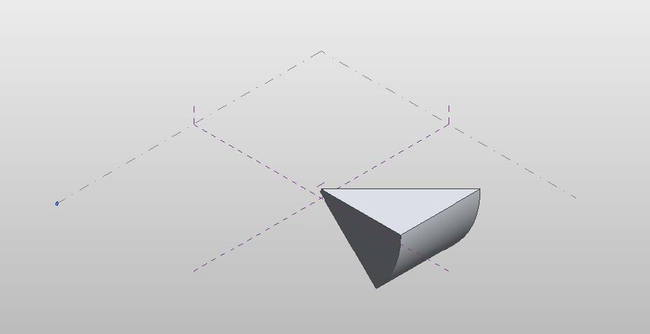
図 55: 作成した回転フォーム