Learn how to display map of plate displacements for a selected load case.
- Continue working in your project or open the project Plate_Analysis.rtd.
Note: The Tutorial files are located in C:\ProgramData\Autodesk\Examples\Tutorials.
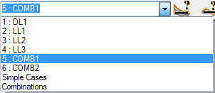
- In the Cases Selection box of the Selection toolbar, expand the Cases drop-down menu and select 5: COMB1.
- Click Results
 Maps.
Maps.
The Maps dialog opens.
- In the Detailed tab select Displacements - u, w: z.
- At the bottom of the Maps dialog select the following options:
- With description,
- Open new window with scale displayed.
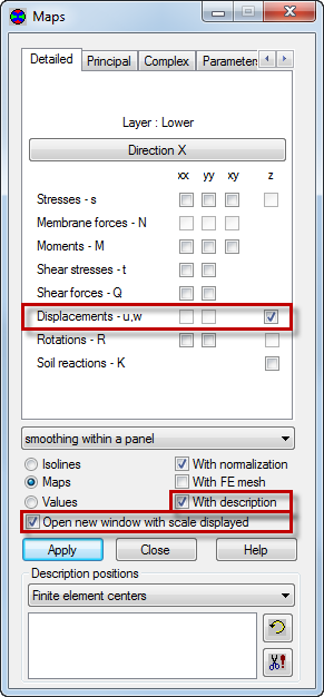
- Click Apply.
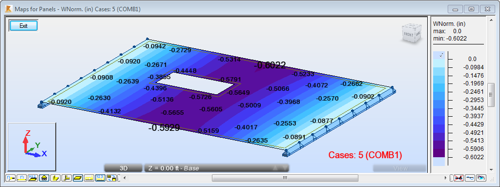
The new window opens and displays the map of displacements for the panel as shown below.
- Click Exit to close the Maps for Panels window.
- Close the Maps dialog.
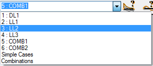
- In the Cases Selection box of the Selection toolbar, expand the Cases drop-down menu and select 3: LL2.
- Click Results Panel Cuts.
The Panel Cuts dialog opens.
- In the Definition tab select Parallel to axis Y, and then type the coordinates:
- (5.00, 15.00).
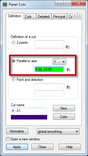
- (5.00, 15.00).
- Go to the Detailed tab, and select Displacements - u, w: z.
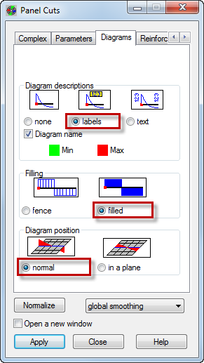
- Go to the Diagrams tab, and select the following options:
- Diagram descriptions: labels,
- Filling: filled,
- Diagram position: normal.
Tip: You can access the Diagrams tab without having to scroll through the tabs. Place the mouse cursor over the arrow near the top left corner of the dialog to display the list of tabs.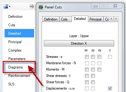
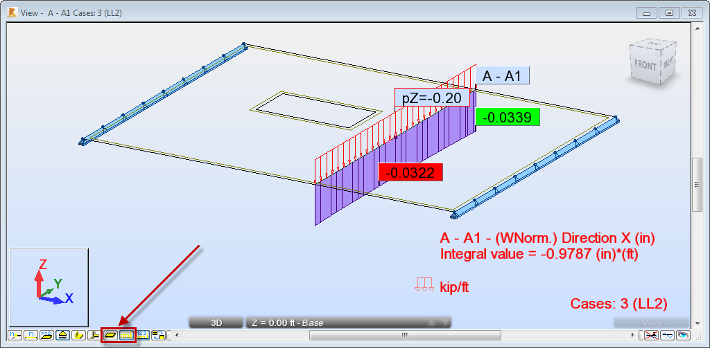
- Click Apply.
- Click
 (Panel Interiors) at the bottom of the drawing area to hide the display of the panel interior. Also, click
  (Load symbols) to display the symbols of loads values.
- Go to the Panel Cuts dialog, in the Cuts tab, and deselect A-A1 cut.
- Click Apply and close the Panel Cuts dialog.
- Save the project as Plate_Results_Maps.rtd.