
This example demonstrates how to create a shader network using a Stingray material and ShaderFX nodes that allow you to blend two textures by painting the vertices.
It is similar to the example "Blend the textures using a Vertex Color node" in the topic "ShaderFX Introductory Sample Workflow"; however, this example uses the Stingray Standard Base node and its associated ShaderFX nodes.
Prepare the Stingray graph:
- Create a Plane in your scene. In the Perspective viewport, press G to turn off grid display,
- Open the
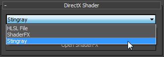
 Material Editor, choose a DirectX Shader material, and apply it to the plane.
 - On the DirectX Shader rollout, choose Stingray from the drop-down list, then click Open ShaderFX.

- In the ShaderFX window, click to highlight the Standard Base node. When 3ds Max prompts you, click Yes to make the shader a custom shader.
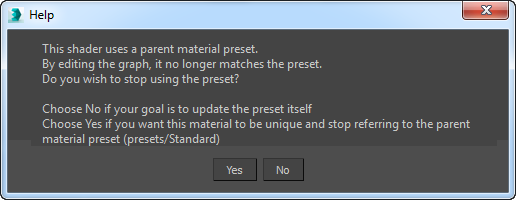
- On the Properties rollout, choose Parent Material
 Custom. When 3ds Max prompts you, click Yes to confirm that this is a custom shader, and to delete the other nodes from the Stingray preset.
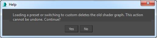
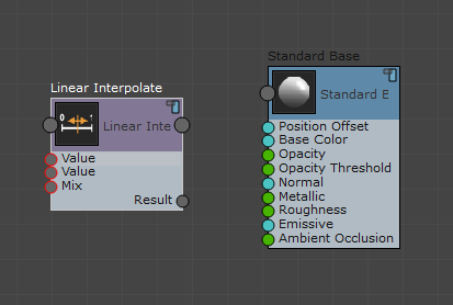
The shader network now contains only the Standard Base node.
Add nodes to the graph:
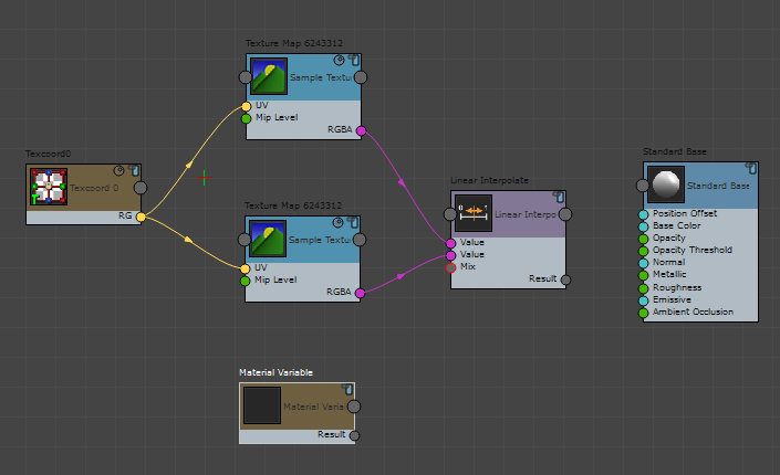
- Add a Math Linear Interpolate node.
- Add two Sampling Sample Texture nodes.
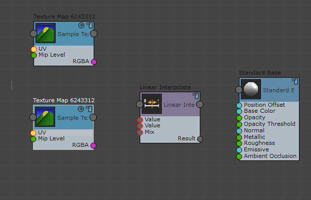
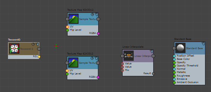
- Add a Vertex Inputs Texcoord0 node.
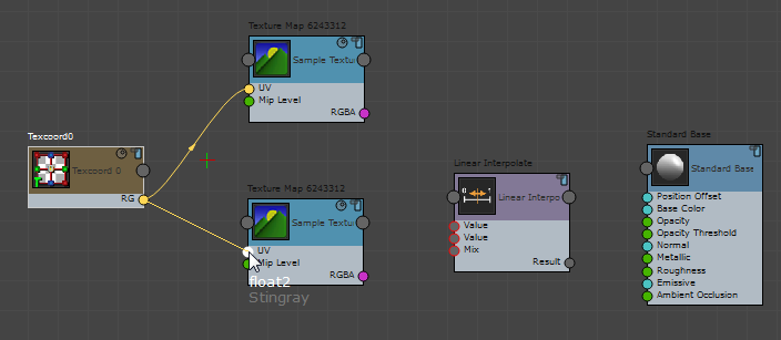
- Wire the RG output of the Textcoord0 node to the UV input of both Sample Texture nodes.
- Wire the RGBA output of each Sample Texture node to a Value input of the Linear Interpolate node.
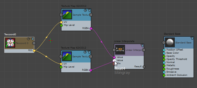
- Wire the RGBA output of each Sample Texture node to a Value input of the Linear Interpolate node.
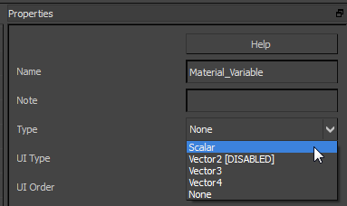
- Add an Input Material Variable node.
- Highlight the Material Variable node, and on its Properties panel choose Type Scalar.
- Wire the Result output of the Material Variable node to the Mix input of the Linear Interpolate node.
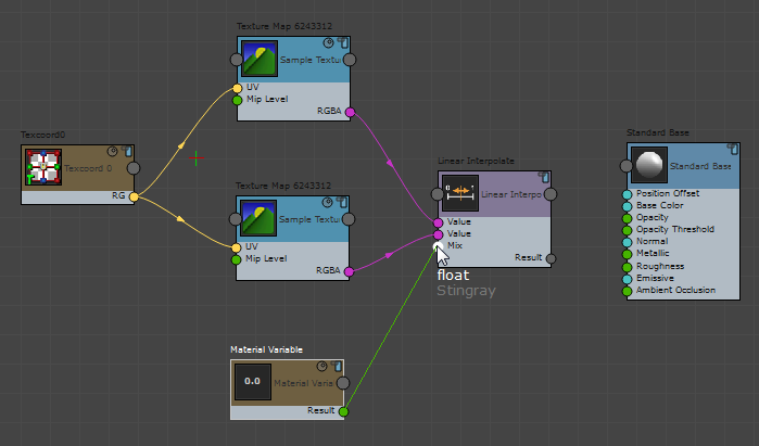
- Wire the Result output of the Linear Interpolate node to the Base Color input of the Standard Base node.
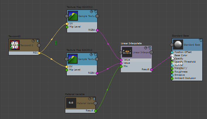
The Stingray graph is now complete. In the next procedure, you adjust the user interface and assign the actual texture maps.
Set up the textures and the BlendMaps parameter:
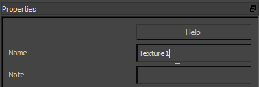
- Click the upper Texture Map node to highlight it, then on the Properties panel change its name to Texture1.
- Change the name of the other Texture Map node to Texture2.
- Change the name of the Material Variable node to BlendMaps.
- Minimize the ShaderFX Editor.
- On the Material Editor Parameters rollout, click the Texture1 button and assign a map; for example, Complete-Right-Side copy.jpg.
- Click the Texture2 button and assign a different map; for example, fac3.jpg.
The textures used for this example are in the \tutorials\sceneassets\images folder, which is available if you download the tutorial files. See http://www.autodesk.com/3dsmax-tutorials-scene-files-2016. (If you use the fac3.jpg map, make sure that Sequence is turned off in the file dialog!)
Use BlendMaps to adjust the blending of the texture maps:
- Change the value of BlendMaps to see the result of blending the two maps. At 1.0, only the second map is visible. Intermediate values give combinations of the two maps.
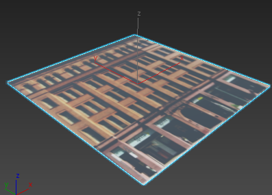
BlendMaps=1.0
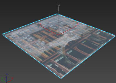
BlendMaps=0.75
At its default value of 0.0, the BlendMaps setting shows only the first texture, as you can see if you move the Material Editor to show the Perspective viewport.
Save your work:
- Open the ShaderFX Editor again.
- On the ShaderFX Editor menu bar, choose File Export Graph.
- On the file dialog, save the new Stingray shader as blend_example.sfx.
- Close the ShaderFX Editor.
- Save the Scene as blend_example.max.