This example problem demonstrates how Advanced Material Exchange can be used to accurately predict the failure load and failure mode for a complex geometry subjected to complex loading.
Problem Description
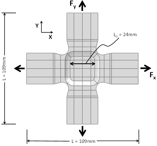
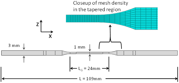
The geometry used in this example is a biaxial cruciform specimen, machined from an injection-molded plaque with a thickness of 3 mm. The central gauge section of the cruciform specimen was machined down in equal amounts on the top and bottom surfaces to produce a thickness of 1 mm. The geometry of the cruciform and the finite element mesh used in the analysis are shown below.
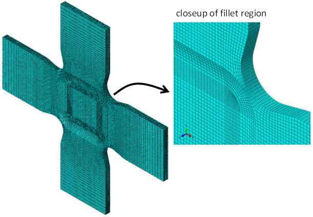
The finite element mesh was produced using 3-D solid hexahedral, 8-noded, reduced integration elements (C3D8R) in Abaqus/CAE. The plaque and the cruciform specimen are made with Extron 3019 HS, a 30% glass fiber-filled material.
The finite element model is designed to simulate six different Fx/Fy load ratios. The results of the simulations are compared with experimental test data performed on several biaxial cruciform specimens.
Load Cases
Six different loading scenarios were simulated for the biaxial cruciform. Five load cases (A, B, C, D, E) were compared with experimental test results.
- Load Case A - Only cross-flow loading (Fx > 0, Fy = 0)
- Load Case B - Fx/Fy = 2.3
- Load Case C - Fx/Fy = 1.2
- Load Case D - Fx/Fy = 0.6
- Load Case E - Only flow direction loading (Fx = 0, Fy > 0)
Results
The image below shows the predicted rupture loads for the six biaxial load ratios. The image also shows the measured rupture loads for the cruciform specimens. The measured results contain two or three replicates at each load ratio to demonstrate the amount of scatter inherent in the test data.
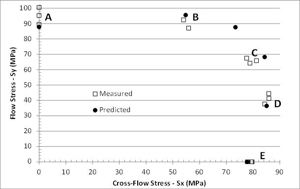
As seen above, the predicted biaxial failure envelope closely matches the size and shape of the measured biaxial failure envelope. The simulated results are even able to predict the strengthening effect that occurs when flow direction loads are accompanied by cross-flow loads.
The images below provide a comparison between the predicted and observed failure modes for load cases A through E.
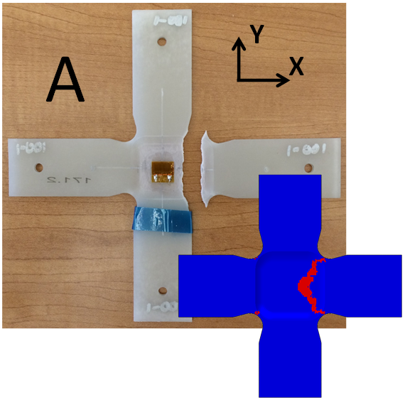
The model for Load Case A correctly predicts that the fracture surface runs from fillet to fillet.
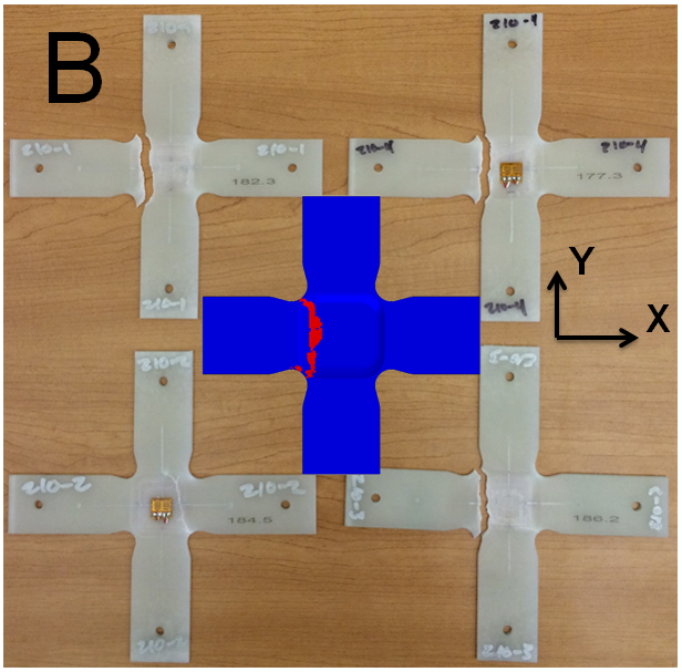
The model for Load Case B correctly identifies the failure mode which runs from fillet to fillet.
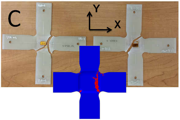
The model for Load Case C predicts a failure mode that differs from the test specimens. However, the fractured areas of the model show aspects of the fracture patterns observed in both test specimens.
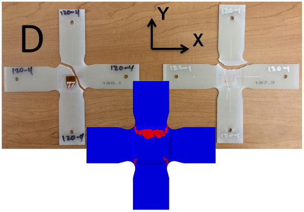
The model for Load Case D predicts a failure mode that shows aspects of the fracture patterns observed in both test specimens.

The model for Load Case E predicts a diagonal fracture surface that differs from the observed horizontal failure.
- The cruciforms are subjected to a variety of load ratios that lead to complex stress states. These stress states are dominated by various combinations of in-plane stress components σxx, σyy, and σxy.
- The cruciforms themselves are geometrically complex. They contain both in-plane and out-of-plane fillets that produce non-homogeneous stress and strain fields with moderate stress concentrations, regardless of the loading.
To highlight this non-homogeneous stress field, consider the plot of the von Mises stress for the uniaxial Load Case E.
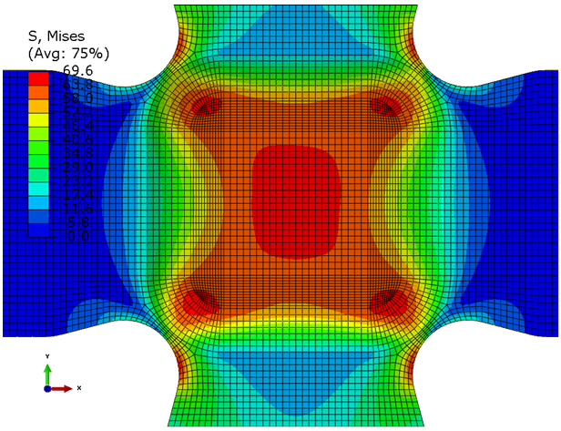
As we can see, the stress field is complex. It includes nine clearly identifiable local maxima. This contour plot also shows a predicted response that is perfectly symmetric since the loading and mesh are both symmetric. It is unlikely that this symmetry exists in the actual cruciform specimens. This may be responsible for the incorrect failure mode predicted for Load Case E above.
Summary
This example problem demonstrates the validity of the multiscale, progressive failure, plasticity model used by Advanced Material Exchange. The results presented here have shown Advanced Material Exchange is able to accurately predict the rupture load and rupture mode for a complex geometry subjected to complex loading.