Advanced Material Exchange can be used to pass the residual strains from your Moldflow model to your structural model in order to predict warpage. Knowledge of these thermal residual strains can be important to accurately predict the structural life of your part.
At the termination of the injection molding simulation, Moldflow assumes the following configuration, let's call it configuration A.
- The part is still confined by the mold
- The part has been cooled to room temperature
- The overpressure has been removed
In configuration A, there is a non-zero stress field that results from non-uniform shrinkage of the injection molded part. The mold exerts a force on the part to hold it in its current shape. If we remove the mold, the residual stress field will cause the part to warp. We'll call this configuration B.
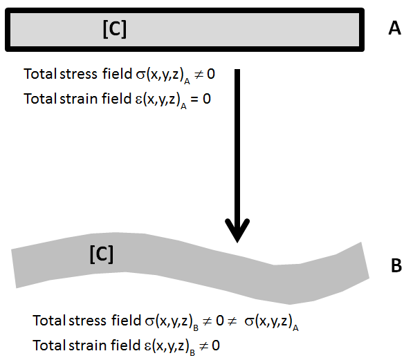
In configuration A, the total stress field predicted by Moldflow is non-zero. When the mold is removed and we proceed to configuration B, the part warps and the total stress field is partially relaxed.
When performing a structural analysis, we always use the undeformed (configuration A) geometry. To get to the warped geometry and associated stress field (configuration B), we do the following:
- Use Advanced Material Exchange to map the residual strains to the structural model
- Create a load step in the structural model that uses the residual strains to deform the part, prior to the application of any mechanical loads. This is our warpage simulation.
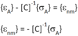
To accomplish this, we need to determine the residual, or non-mechanical strains from configuration A. First, we write the equation for the total stress field in configuration A.
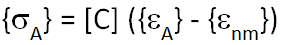
Now we solve for the non-mechanical strains. Recall that the total strain field in configuration A is zero.
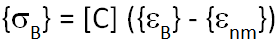
We can now use these non-mechanical strains as inputs for the initial loading of the structure (warpage simulation). This is analogous to driving the problem with αijΔT.
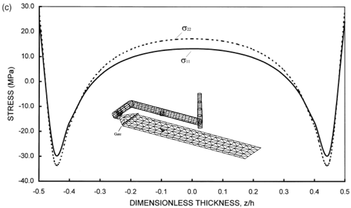
At this point, we can evaluate the post-warpage stress field as predicted by the Helius PFA solver and compare to the traditional stress fields published in academic research papers. The image below shows the through-thickness stress field for a rectangular shaped coupon produced by injection molding [15].
To compare the stress fields, we created a similar rectangular shaped part and examined the stress distribution in the flow direction as predicted by Helius PFA using the non-mechanical strains from Moldflow. The image below shows a cross-section of the part and the predicted stress field. The image in the lower right depicts the superimposed curve produced by Zheng [15] shown in yellow, and the curve predicted by Helius PFA shown in white. These curves represent stress field for the unconstrained, warped part, with no external loading.
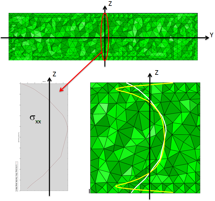
In the simulated results we notice the core of the part is in tension and the surface is in compression. This behavior correlates well with the academic research. Given the mesh density used in this example, it is impossible to capture the sign reversal predicted by Zheng in the outermost portion of the part. However, this method does a good job of representing the compressive strain energy in the outer fourth of the part.