After the part and material have been created, a composite layup section is created.
As mentioned previously, our composite part will have a [45/0/-45/90]3S layup. We will create a coordinate system from which we can rotate each of the four angles in our layup.
- Click the Geometry tab and specify Create, Coord, 3Point.
- In the Coord ID List box, name the coordinate system 11 and set the Type to Rectangular.
- Set the Origin at [0 0 0], the Point on Axis 3 to [0 0 1], and the Point on Plane 1-3 as [0 1 0].
- Click Apply.
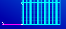
The new coordinate system should appear as shown below.
Now that we have created the base coordinate system, we can create the layered composite section.
- Click Properties > Composite > Laminate.
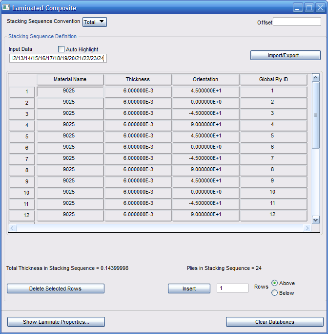
- In the dialog that appears, create a 24 ply laminate using the 9025 material name (or the appropriate material ID for the Tutorial_1 material created previously). To add the material, click 9025 from the Existing Materials list until 24 plies have been added.
- In the Laminated Composite dialog window, set the thickness of each layer to 0.006.
- Select the first row of the Orientation column and enter the following in the Input Data field: 45/0/-45/90/45/0/-45/90/45/0/-45/90/90/-45/0/45/90/-45/0/45/90/-45/0/45 then hit Enter.
- Select the first row of the Global Ply ID column and enter the following in the Input Data field: 1/2/3/4/5/6/7/8/9/10/11/12/13/14/15/16/17/18/19/20/21/22/23/24 and hit Enter.
- The Laminated Composite window should appear as shown below:
- On the Materials form, name the laminate Ply and click Apply.
The final steps modify the existing solid property to a layered solid composite property (PCOMPLS).
- On the Element Properties form (Properties > 3D Solid Properties > Solid), select Modify, 3D, Solid.
- In the New Property Set Name box enter 2.
- Select Laminate from the Options menu and click the Modify Properties button.
- Enter the laminate name Ply.
- Click in the Material Orientation box and select coordinate system 11 from the viewport.
- Specify the Thickness Direction 3D as Element Z Direction and the SLCOMP Integration Scheme as Assumed Strain. Click OK.
- Click Select Application Region and select the entire model. Click Add. Note: You may have to select the Hex Element button to enable selection of the model elements.

- Click OK and click Apply on the Element Properties form.