Create two additional boundary conditions that impose a pure mode I loading to the beam.
The beam is loaded using imposed displacements because it results in a much more gradual failure process than a comparable loading by applied forces.
- In the Load/Boundary Conditions form (Loads/BCs > Displacement Constraint), create a new set called top_disp_load.
- Click the Input Data button, enter <, 10 ,> in the Translations field and click OK.
- Click the Select Application Region button and select all nodes that lie on the top edge at the end of the beam (x = 150, y = 3). Add the nodes to the Application Region and click OK.
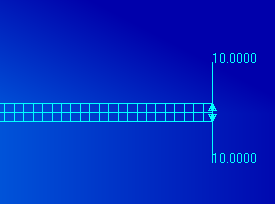
- Click Apply in the Load/Boundary Conditions form to create the set. The viewport should now appear as shown below.
- Create another set named bottom_disp_load with <, -10 ,> in the Translations field.
- Select all of the nodes on the bottom surface at the end of the beam (x = 150, y = 0). Add the nodes to the Application Region and click OK.
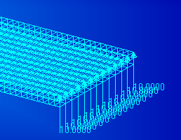
- Click Apply in the Load/Boundary Conditions form to create the set. The viewport should now appear as shown below.