Defining the part geometry is generally the first step in the development of a finite element model.
Here, the plate geometry is sketched and extruded to generate a solid part.
- Open Abaqus/CAE. Some of the screenshots presented in this tutorial were taken from older versions of Abaqus. Consequently, results may differ slightly for other versions of CAE.
- With Abaqus/CAE open, select the .
- In the Model Tree, double-click the Parts container
 or click from the main toolbar.
 - In the Create Part dialog box that appears, name the part Composite_Plate and accept the default selections of 3D, Deformable, Solid, Extrusion. Adjust the Approximate Size to 1.
- Using the Create Lines: Rectangle tool
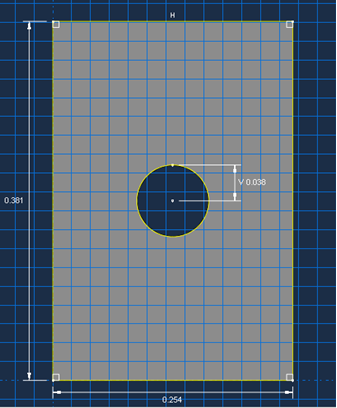
 , create a rectangle with the starting corner at coordinates 0, 0 and the opposite corner at coordinates 0.254, 0.381.
 - Using the Create Circle: Center and Perimeter tool
 , create a circle with the center point at coordinates 0.127, 0.1905 and the perimeter point at coordinates 0.127, 0.2286. The section sketch is now complete and is shown below with dimensions.
 - Click the
 button followed by the
  button to finish the sketch.
 - In the Edit Base Extrusion dialog box that appears, enter a value of 0.001016 m in the depth field since there are 8 plies with thickness 0.000127 m. Click OK.