Create two additional boundary conditions that impose a pure mode I loading to the beam.
The beam is loaded using imposed displacements because it results in a much more gradual failure process than a comparable loading by applied forces. First a coupling constraint is applied to the nodes on the outer edge of the beam to allow for a simple determination of total reaction force during post-processing.
- Select Preprocessor > Coupling / Ceqn > Cupl DOFs w/Mstr.
- Pick all nodes on the left edge of the beam (x = 100, z = 1) as shown below, making sure the top-most node (y = 10) is picked first. Click OK.
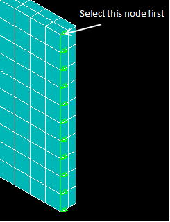
- Set the reference number to 100 and the degree-of-freedom label to UZ. Click OK to complete the coupling definition.
As a consequence of the coupling constraint, a displacement in the z-direction applied to the node highlighted above will result in the same z-displacement applied to the remaining nodes in the constraint definition.
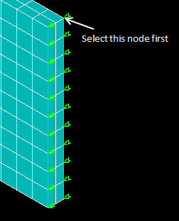
- Repeat steps 1-3 for the opposite side of the beam (x=100, z=0), assigning a different reference number (e.g. 200) to the constraint equation.
- Select Preprocessor > Loads > Define Loads > Apply > Structural > Displacement > On Nodes and select the first node from step 2 (x = 100, y = 10, z = 1).
- Apply a UZ value of 10 and click OK.
- Repeat steps 5-6 and apply a UZ displacement of -10 to the node shown in the image above (x = 100, y = 10, z = 0).