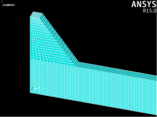
We will specify manual size controls on the edges of our beam to control the number of elements in each direction.
- Click Preprocessor > Meshing > Size Cntrls > Manual Size > Lines > Picked Lines.
- Use the graphics window to select the 4 lines of the beam parallel to the global x-axis and click OK.
- In the dialog that appears, specify 700 in the NDIV box and click OK.
- Repeat steps 1-3, selecting the 4 lines of the beam parallel to the global y-axis with NDIV = 25.
- Repeat steps 1-3 once again, selecting the 4 lines of the beam parallel to the global z-axis with NDIV = 1.
Now we are ready to mesh the beam.
- Open the Mesh Tool (Preprocessor > Meshing > Mesh Tool).
- In the dialog that appears, click the Set button next to the Global option under the Size Controls, enter 1.0 in the Size entry box and click OK.
- Select the Hex and Mapped radio buttons and click the Mesh button.
- Select the beam volume from the graphics window and click OK.
To mesh the rubber pad, we will just use the size controls.
- Open the Mesh Tool again (Preprocessor > Meshing > Mesh Tool).
- In the dialog that appears, click the Set button next to the Global option under the Size Controls, enter 0.2 in the Size entry box and click OK.
- Select the Hex and Mapped radio buttons and click the Mesh button.
- Select the rubber pad volume from the graphics window and click OK.
