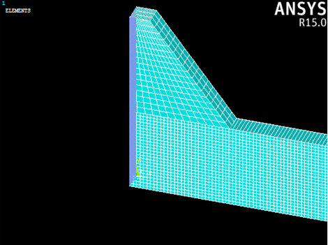
First we will create boundary conditions that prevent the left end of the beam from displacing in the global x-direction. Since we are using a half-symmetry model, we must enforce this condition.
- Select Preprocessor > Loads > Define Loads > Apply > Structural > Displacement > On Areas.
- Use the graphics window to select the end surface of the beam and the end surface of the rubber pad and click OK.
- In the dialog that appears, select UX and enter a displacement of 0 and click OK.
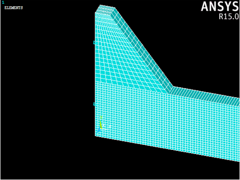
Now we will prevent the entire model from displacing in the global z-direction. This enforces a plane strain condition.
- Select Preprocessor > Loads > Define Loads > Apply > Structural > Displacement > On Nodes.
- Use the graphics window to select all nodes of the model and click OK.
- In the dialog that appears, select UZ and enter a displacement of 0 and click OK.
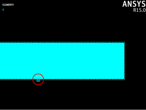
Next, we can apply a displacement constraint to simulate the support for the 3-point bending test.
- Select Preprocessor > Loads > Define Loads > Apply > Structural > Displacement > On Nodes.
- Use the graphics window to select the nodes shown below and click OK (If you followed all of the steps thus far, the appropriate nodes to select are numbered: 1392, 1393, 18869, and 18870).
- In the dialog that appears, select UY and enter a displacement of 0 and click OK.
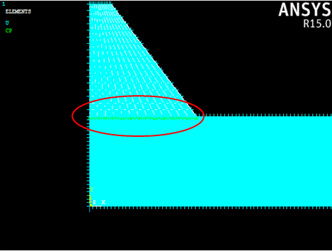
The final boundary condition will tie the rubber pad to the beam.
- Select Preprocessor > Coupling / Ceqn > Couple DOFs.
- Select all of the nodes on the bottom of the rubber pad and click OK.
- Assign a reference number of 1 and select the UY degree-of-freedom label. Click OK.