The example problem consists of a conical, composite sandwich structure subjected to a quasi-static axial compressive load that is monotonically increased until global structure failure occurs.
The example problem is similar to the load-controlled tests that are part of the composite structure's flight qualification testing. The image below shows the finite element mesh used to represent the conical composite structure, the load head, and the load head adapter.

Four actuators are used to apply concentrated vertical compressive forces to a load head that sits on top of the conic structure (above). The table below lists the compressive forces applied to each of the four positions on the load head. These forces result in a uniform vertical compressive load where 100% loading corresponds to a total vertical compressive force of 200,000 lbs.
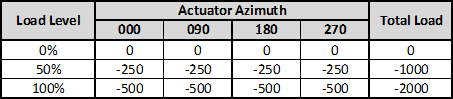
- Loads are in kips
- Loading is quasi-static and is linearly ramped up
- Negative sign indicates a compressive force
An adapter is used to connect the load head to the conic structure. For simplicity, the adapter and load head are considered rigid when compared to the composite conic, therefore, an arbitrarily large elastic modulus was assigned to the isotropic material used for both the load head and the adapter. As seen above, an access door is cut through the side of the conic structure. The boundary conditions for the conic structure are provided by constraining the entire bottom surface of the conic structure using fixed boundary conditions (displacements in the 1, 2 and 3 directions are constrained to have zero displacement).
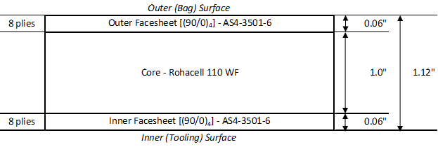
The composite conic structure features a sandwich panel construction. The through-the-thickness profile of the sandwich panel (below) is uniform in both the hoop and axial directions on the conic. The inner and outer composite face sheets of the sandwich construction have a [(90/0)4] layup as measured from the inside surface (0° is in the axial direction, 90° in the hoop direction). Each of the composite plies is 0.0075" thick and composed of carbon/epoxy AS4-3501-6. The 1" thick core is an isotropic foam material (Rohacell 110 WF).
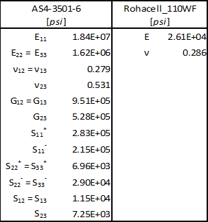
Material properties for AS4-3501-6 and Rohacell 110 WF are provided below. A post failure stiffness ratio of 0.1 is used for matrix failure, and 0.01 is used for fiber failure.
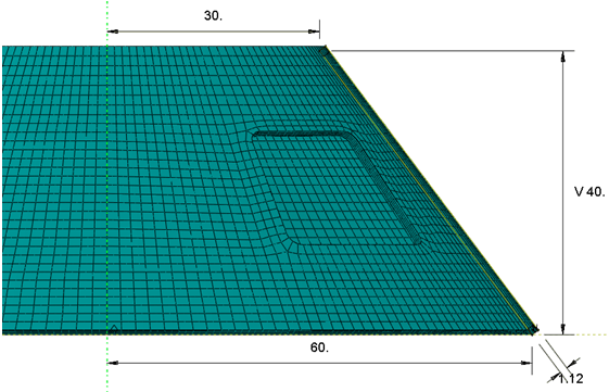
The image below provides the dimensions for the composite conic structure.