Defining the part geometry is generally the first step in the development of a finite element model.
Here, the plate geometry is defined to generate a 3-dimensional part.
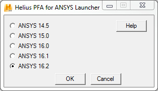
- Open ANSYS Mechanical APDL using the
Helius PFA for ANSYS Launcher tool shown below. This tool launches ANSYS with the necessary environment variables to run
Helius PFA with ANSYS.
- This tool is installed with the product and is located at the following path:
%install_dir%\bin\ansys-helius-launcher.exe
- It can also be found by going to
, or by clicking on the desktop icon
- This tool is installed with the product and is located at the following path:
- Click the Run button in the ANSYS Mechanical APDL Product Launcher. The ANSYS GUI will appear.
- Click .
- In the dialog box that appears, enter the following values and click
OK:
- WP X = 0
- WP Y = 0
- Width = 0.254
- Height = 0.381
- Depth = 0.001016
- Click .
- In the dialog box that appears, enter the following values then click
OK:
- WP X = 0.127
- WP Y = 0.1905
- Radius = 0.0381
- Depth = 0.001016
- Click .
- Select the plate from the Graphics Window. A message will appear noting there are two volumes at this location. Make sure Volume 1 is the Picked Volume and click OK.
- Click OK in the Subtract Volumes dialog box.
- Select the cylinder from the Graphics Window. Make sure Volume 2 is the Picked Volume and click OK.
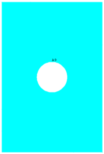
- Click OK in the Subtract Volumes dialog box. The plate geometry is now defined. The plate should appear as shown below.