Define the cross-section geometry of the tube/beam.
As shown below, there are six regions that provide information about the geometric properties of the tube/beam cross section:
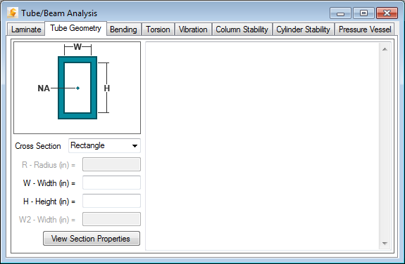
- A drop-down menu to select the desired cross-section for the analysis. Available geometries are Rectangle, Plate, Circle, Ellipse, Channel, and C/I/T/Hat Sections. Note, for the Cylinder Stability option, only Circle cross-sections are available.
- A pictorial depiction of the selected cross section is shown in the window above the drop-down. The dimensions required to define the cross-section geometry and the approximate location of the neutral axis (NA) are depicted in the drawing.
- Text field to enter the radius (if applicable) of the cross-section.
- Text field to enter the width (if applicable) of the cross-section.
- Text field to enter the height (if applicable) of the cross-section.
- Text field to enter the secondary width (if applicable) of the cross-section.
- By clicking the "View Section Properties" button, the following cross-sectional properties (based upon the cross-section, dimension(s), and laminate definition) are calculated and displayed:
- Thickness of composite laminate, t
- Area moment of inertia of tube/beam cross-section, I
- Beam stiffness (bending and shear), E
- Polar moment of inertia of tube/beam cross-section, J
- Modulus of Rigidity, G
- Radius of gyration, Rg
- Cross-sectional area, A
- Distance to extreme fiber from neutral axis, C