A labeling strategy contains settings for the content, the layout and the arrangement of a label.
Add / rename the labeling strategy
The list of labeling strategies can be modified. New strategies can be added or existing strategies can be renamed.
| Button | Function |
|
|
Define a new labeling strategy. A new item is inserted into the list and changes can be made to it from the controls. |
|
|
Rename a labeling strategy. The current settings are saved under a different name. |
Set the label position
The label position is set using the options in the "Text direction and combining labels" area.
| Parameter | Description |
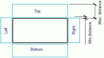
| Max distance |
|
| Text direction |
|
| Place along the object |
|
| Arrange beam label according to compass |
|
| Definition of the leader line |
Underscored Text only |
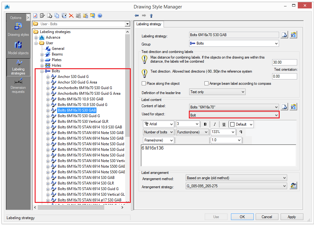
Set the label content
The label content can be defined using the label designer in the "Label content" area. Options for the format definition (font, frames, colors etc.) are also available.
Setting the label type
The label type is selected from the Label content drop-down list. The list of label types can be modified. New types can be added or existing types can be renamed.
| Button | Function |
|
|
Define a new label type. A new item is inserted into the list and changes can be made to it from the controls. |
|
|
Rename a label type. The current settings are saved under a different name. |
The Used for objects option states for which model objects to apply the definition. This setting influences the selection of the label style on the tree panel after opening a drawing style.
Example:
For bolts, the Used for object option lists Bolt or All objects.
Setting the label format
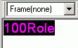
Select a font type, size and color. Optionally a boundary around the text may be used:
- Select the tokens in the preview area.
- Select a boundary. Four boundary types are available:
Option Boundary Example Rectangular 

Rectangular with fillets 

Hexagonal 

Circular 

- Set the boundary distance from the text.
In the preview area, the text is displayed, as it will appear on the drawing. The preview area only displays the text and not the formatting.
A label contains a combination of individual variables and additional texts.
Click Variable ![]() to set the label content as variable.
to set the label content as variable.
| Meaning | Model objects | Variable |
| Section name | Beams | %ProfName |
| Number of members | Beams | %RodCount |
| Material | Title, Beams, Plates, Bolts, Shear Studs, Special Parts | %Material |
| Coating | Title, Beams, Plates, Bolts, Shear Studs, Special Parts | %Coating |
| Name (Denotation) | Title, Beams, Plates, Bolts, Shear Studs, Special Parts | %Denotation |
| Part mark | Title, Beams, Plates, Special Parts, NC | %PosNum |
| Length | Title, Beams, Plates, Bolts, Holes, Shear Studs | %Length |
| Width | Plates | %Width |
| Thickness | Plates | %Thickness |
| Bolt standard | Bolts, Shears Studs | %Norm |
| Bolt diameter | Bolts, Holes, Shears Studs | %Diameter |
| Hole diameter | Bolts | %HoleDiameter |
| Number of bolts | Bolt, Holes | %BoltCount |
| Assembly group | Beam, Plates, Special Parts, NC | %Assembly |
| Commodity | Beam, Plates, Bolts, Shear Studs, Special Parts | %ItemNumber |
| Vertical depth | Holes | %SunkDepth |
| Others | Title, Beams, Plates, Bolts, Special Parts | %Note |
| Single part mark | Title, Beams, Plates, Special Parts, NC | %SinglePartPosNum |
| Main part mark | Title, Beams, Plates, Special Parts | %MainPartPosNu |
| Hole type | Holes | %Role |
| Thread (left-hand / right-hand) | Holes | %Tapping |
| Bolt assembly | Bolts | %Set |
| Head diameter | Holes | %HeadDiameter |
| Countersinking angle | Holes | %Alpha_e |
| External name 1 | Beam, Plates, Bolts, Special Parts | %ExtName1 |
| External name 2 | Beam, Plates, Bolts, Special Parts | %ExtName2 |
| External name 3 | Beam, Plates, Bolts, Special Parts | %ExtName3 |
| External name 4 | Beam, Plates, Bolts, Special Parts | %ExtName4 |
| Quantity | Title, Beams, Plates, Special Parts | %Quantity |
| Name | Title, Beams, Plates, Bolts, Shear Studs, Special Parts | %Name |
| Position | Title, Beams, Plates, Special Parts | %Position |
| Quantity in main part | Title, Beams, Plates, Special Parts | %MainPartQuantity |
| Scale | Title | %Scale |
| Date | Title | %Date |
| USDate | Title | %USDate |
| Time | Title | %Time |
| Day | Title | %Day |
| Month | Title | %Month |
| Year | Title | %Year |
| Hour | Title | %Hour |
| Minute | Title | %Minute |
| Sign ø | Title | %%c |
| Sign % | Titl | %%% |
| Sign ° | Title | %%d |
| Sign ± | Title | %%p |
| User Attribute 1 | Beams, Plates, Special Parts | %UserAttr1 |
| User Attribute 2 | Beams, Plates, Special Parts | %UserAttr2 |
| User Attribute 3 | Beams, Plates, Special Parts | %UserAttr3 |
| User Attribute 4 | Beams, Plates, Special Parts | %UserAttr4 |
| User Attribute 5 | Beams, Plates, Special Parts | %UserAttr5 |
| User Attribute 6 | Beams, Plates, Special Parts | %UserAttr6 |
| User Attribute 7 | Beams, Plates, Special Parts | %UserAttr7 |
| User Attribute 8 | Beams, Plates, Special Parts | %UserAttr8 |
| User Attribute 9 | Beams, Plates, Special Parts | %UserAttr9 |
| User Attribute 10 | Beams, Plates, Special Parts | %UserAttr10 |
| Model role | Beam, Plates, Bolts, Special Parts | %Role |
| Assembly Length | Title, Beams, Plates, Special Parts | %AssemblyLength |
| Flange Thickness | Title, Beams, Plates, Special Parts | %FlangeThickness |
| Web Thickness | Title, Beams, Plates, Special Parts | %WebThickness |
| Axis Length | Title, Beams | %AxisLength |
Special symbols can be inserted using ASCII codes. To insert a symbol, a number combination must be entered with the ALT-key being pressed.
| Symbol | ¢ | µ | ½ | ± | ¼ |
| Code | 155 | 230 | 171 | 241 | 172 |
The available symbols are found in the Windows Character Map accessible from the Windows start menu (Start - Programs - Accessories - System Tools - Character Map).
Setting the label arrangement
![]()
- Select an arrangement method. Two options are available:
| Arrangement method | Description |
| Based on angles |
|
| Based on areas |
|
- Select an arrangement strategy from the list. To configure an arrangement strategy click Set
 .
.
Modify the arrangement strategy
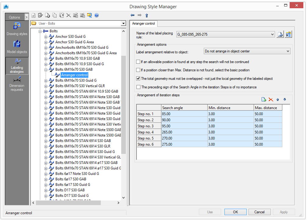
Figure 56: Label arrangement
Select a label-placing rule from the list. The existing rules can be renamed and new rules can be added.
The names of the rules contain the searched angle range.
| Button | Function |
|
|
Define a new label type |
|
|
Rename a label type |
Arrangement options
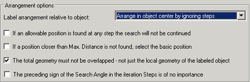
- If, in the iterative steps, an accepted position is found, the following steps will not be checked. This may save time but it does not always give an optimum position.
- If, in the range between MinDistance and MaxDistance, no position can be found, the basis position will be selected (usually the object center).
- View the complete detail view (global) for the position search or view only the local object to be labeled.
- The preceding sign of the moving direction is not being considered therefore less iterative steps are necessary.
Label arrangement relative to object
Three options are available:
| Button | Function |
| Arrange in the center of the object by ignoring steps |
|
| Arrange in the center of the object using steps |
|
| Do not arrange in the center of the object |
|
Manage the iteration steps
The toolbar contains all the necessary management functions:
| Button | Function |
|
|
Add an iteration step |
|
|
Delete the selected iteration step |
|
|
Move the selected iteration step up |
|
|
Move the selected iteration step down |
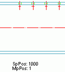
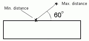
Set the search angle and the minimum and maximum distance for each iteration step.
This option defines the search direction (angle) for a free position. This option is dependent on the system settings in AutoCAD â (Menu format - Units - Direction). By default, 0° is in the East and it is measured anticlockwise.
This option defines the smallest distance from the object that is allowed.
This option defines the largest distance from the object that is allowed.