Setting the view direction defines the way the model objects are shown in the view.
For example, the main direction relative to the coordinate system (front, top, bottom etc.) and the main direction relative to the object that will be shown in the view can be defined.
The advanced options for defining the view direction and the viewports are available on the View direction and model box tab. They are accessed by two methods:
- On the tree panel, select the View direction and model box branch
or
- On the View definition tab, in the "View direction and model box" area, click Set
 .
.

View direction and model box
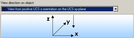
Select a pre-configured view direction from the list (e.g. front, top, left, etc.). The existing view directions can be renamed and new definitions can be added.
| Button | Function |
|
|
Define a new system and box. A new item is inserted into the list. |
|
|
Rename a strategy. Saves the current settings under a different name. |
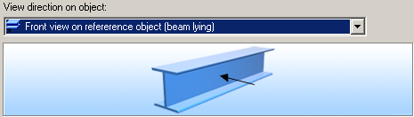
The way the reference object is viewed (e.g., from the front, right, active UCS, intersection) is determined by theView direction on object .
Remarks:
- For General arrangement drawings, use:
- For Workshop drawings, in most of the cases, use:
Z-viewport
The Z-viewport defines the view depth of the front and rear (Z-orientation of the UCS).
| Option | Function |
|
Relative to XY view plane |
Detailing relative to the XY plane of the UCS |
|
Relative to object view |
Automatic end plates detailing |
|
Front and rear at next cut |
This option is used only for options whose names start with Cross sections… for the View direction on object. |
XY-viewport
The XY-viewport defines the height (Y-orientation of the UCS) and the width (X-orientation of the UCS) of the viewport. There are three available options:
| Option | Function |
|
Automatic |
|
|
Fixed |
Enter X-, Y-delta values in the corresponding fields |
|
Select |
By selecting window points in the model |
Enlarging the viewport to show additional parts
Enlarge the presentation of the viewport to show additional elements (e.g. filler pates). Normally, the viewport is as large as the reference object with attached parts.