There are several options for setting the beam end orientation inside a detail.
Example: Beam end orientation settings
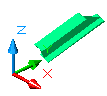
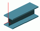
A beam with the starting coordinates 200, 500, 300 and the ending coordinates 500, 1500, 800 has at the end an inclined cut.
The following beam end orientation settings are available:
| Beam end orientation | Example |
|
Highest XYZ-Coordinate left side |
From both ends, the highest X-, Y- or Z- coordinate is calculated. The corresponding end of the beam is situated on the left side of the drawing. 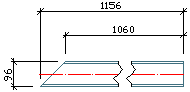
|
|
Highest XYZ-Coordinate right side |
From both ends, the highest X-, Y- or Z- coordinate is calculated. The corresponding end of the beam is situated on the right side of the drawing. 
|
|
Highest Z-Coordinate left side |
From both ends, the highest Z-coordinate is calculated. The corresponding end of the beam is situated on the left side of the drawing. In the example, the end point has the highest Z-coordinate: Z=800. 
|
|
Highest Z-Coordinate right side |
From both ends, the highest Z-coordinate is calculated. The corresponding end of the beam is situated on the right side of the drawing. 
|
|
Start point left side |
The start point of the beam is situated on the left side of the drawing. (Depends on how the beam was created.) 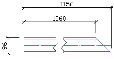
|
|
Start point right side |
The start point of the beam is situated on the right side of the drawing. (Depends on how the beam was created.) 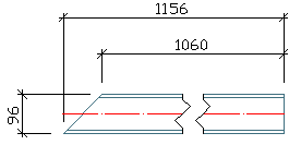
|
Views Orientation
The orientation of views defines how the members are oriented on the drawings, e.g., the columns can always be shown vertically or horizontal. The following options are available:
| Orientation of the views | Description |
|
Standard |
Without special orientation. Recommended for details and views. |
|
Model Z Left |
If the columns are represented lying, they will be tipped over to the left. This means that the base point is always on the right side on the drawing. |
|
Model Z Right |
If the columns are represented lying, they will be tipped over to the right. This means that the base point is always on the left side on the drawing. |
|
Model Z Top |
Side lying at the top in the model is also at top in the detail. |
|
Perpendicular |
The longitudinal beam axis is vertical on the drawing. The longer plate side is placed vertically on the drawing. |
|
Reversed |
The same principle is applied as for "Perpendicular" orientation of views. The coordinate system of the view is rotated by 180 °. |
Automatic Clipping
The drawings are automatically well filled, so that there is no empty space on the left and on the right, and also above and below of the (main) views.