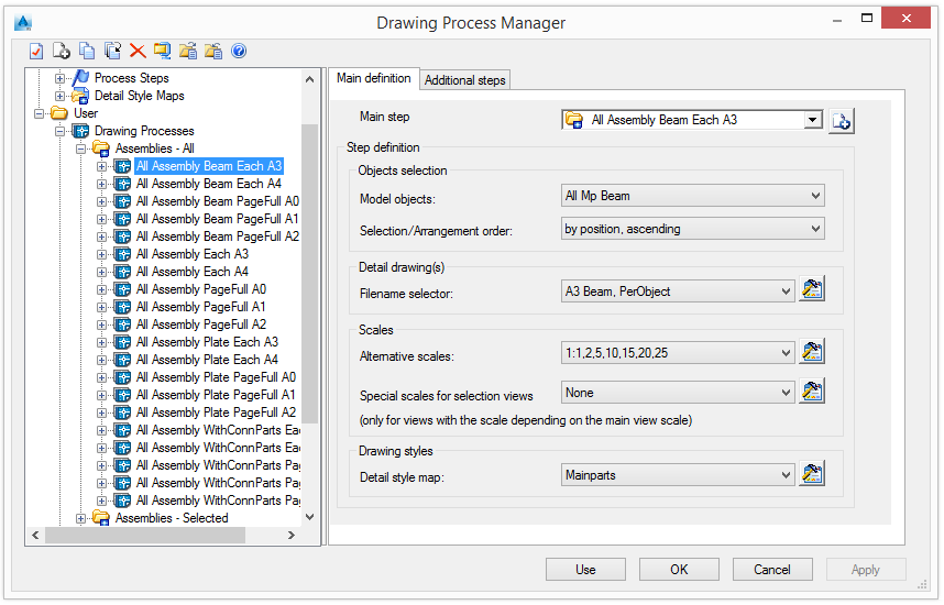
Set the process definition properties in the Main definition and Additional steps tab.
A process can have more than one step.
The first step of a process - the main step - determines the process behavior and configuration. If the main step cannot fit a detail in a prototype, additional steps are used.
Select the main step
Select a main step from the list. The list of steps can be modified.
Add a new step
- Click Add
 .
.
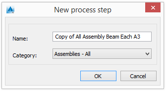
- Enter the new process name.
- Select a category.
A new step is added to the list with the current step definition.
Select model objects
In the "Objects selection" area, select a model object to be detailed by the selected process and the arrangement option.
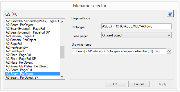
The drawing name is created based on the filename selector rule.
Filename selector
Select a filename selector from the list. Click Properties ![]() .
.
The list of filename selectors can be modified.
| Button | Function |
|
|
Add a new file selector |
|
|
Delete a file selector |
Prototype
Enter the name of the prototype file.
Close page
Select a close page option. Three options are available.
| Option | Description |
| On next object | The next object is displayed on a new page |
| On next main part | The next main part is displayed on a new page |
| On page full | Displayed on the full page |
Name of the detail drawing
- Click
 and select the information to add in the drawing name from the options in the displayed list.
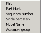
| Option | Description |
| Flat |
|
| PosNum |
|
| SequenceNumber |
|
| SinglePartPosNum |
|
| ModelName |
|
| Assembly |
|
Example:
A4-Detail %Flat(03).dwg
Alternative scales
A process creates the detail with the drawing style scale used for the object. If the detail does not fit in the selected prototype, the process will try the alternative scales.
- Select the alternative scales from the list.
- Click Properties
 .
. 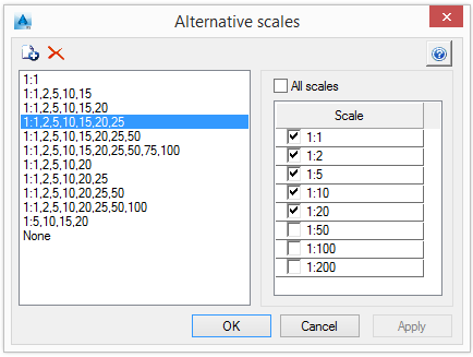
The list of alternative scales can be modified.
| Button | Function |
|
|
Add a new alternative scale. A copy of the selected scale is added to the list. |
|
|
Delete an alternative scale |
Special scales for a view
Special scales can be selected for views with the scale depending on the main view scale.
- Select a special scales item from the list. Click Properties .
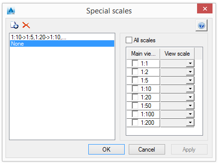
Scales are managed in the same manner as alternative scales.
Detail styles
- Select a detail style map from the list.
- Click Set .
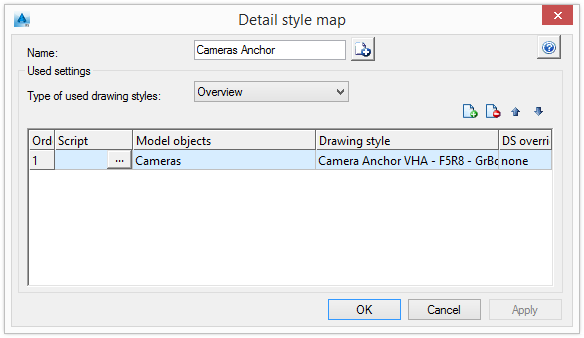
- Select a type of used detail styles from the list.
- In the table, an appropriate detail style for the process is assigned to the elements of the 3D model (Model objects). This assignment determines the presentation of the model elements on the drawing.
Additional steps
If the process cannot fit the detail with any scale, it will continue with the next step from the Additional steps of the process definition. If, after all the steps, the process still cannot fit the detail in the page, the detail is created with the last style and scale.
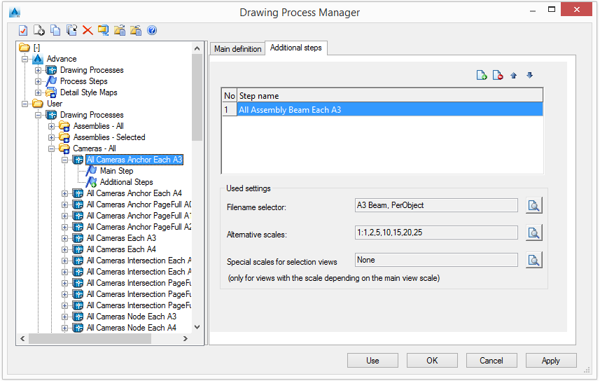
Add as many additional steps as necessary.
The configuration of the settings used for the additional steps is displayed in the "Used settings" area.