A 3D view of an assembly can be added to a main part drawing in order to create a better image of the detailed element.
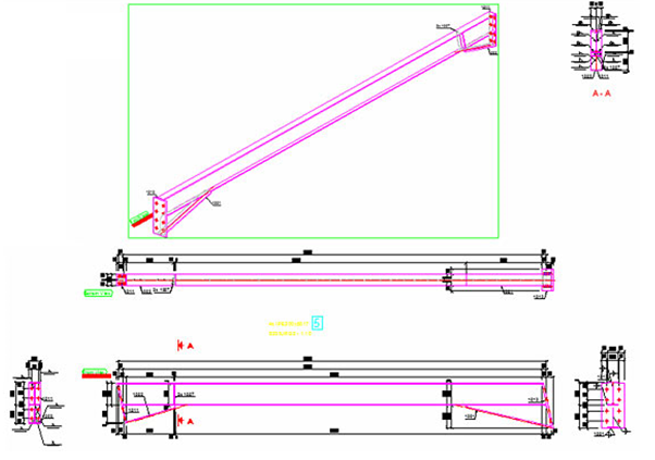
The isometric view gives the drawing a more dynamic look. To add this view in a drawing style, perform the steps described in the following example, where the Tie beam - AutoIntersections drawing style is modified to display the isometric view. After modifying the drawing style, a detail drawing of a rafter beam is created to display the change:
-
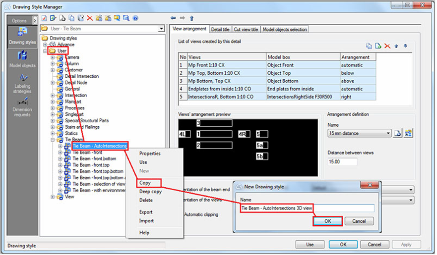
Open the Drawing Style Manager and from the User category copy the Tie beam - AutoIntersections drawing style and name it Tie beam - AutoIntersections drawing style.
-
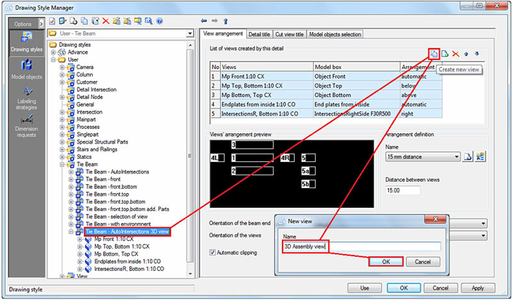
Create a new view and name it 3D assembly view.
-
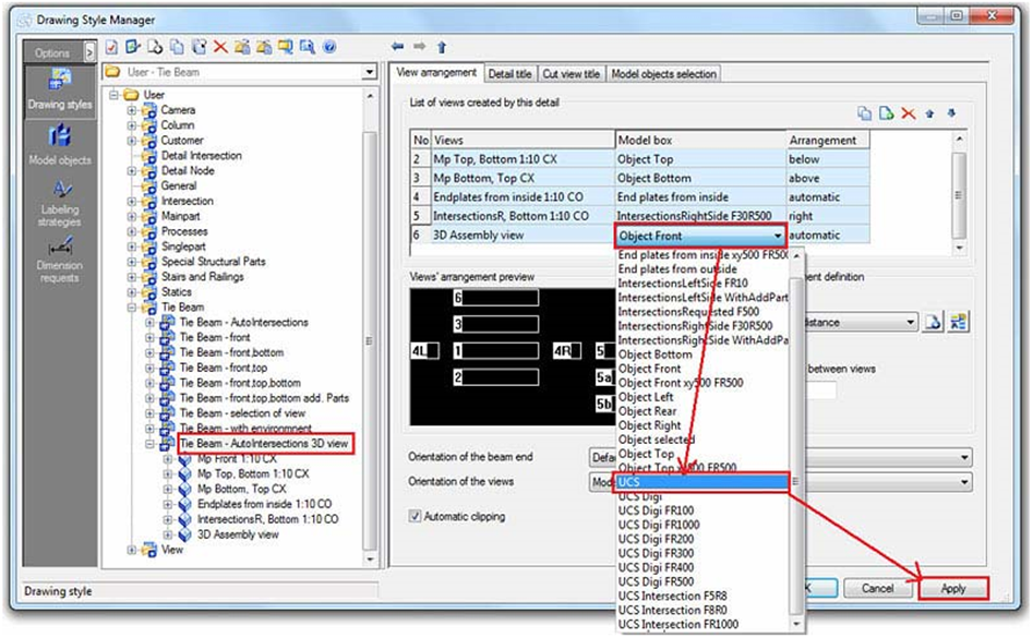
For the newly created view, change the view direction and model box name to UCS. Click the Apply button to save the changes and close the Drawing Style Manager.
-
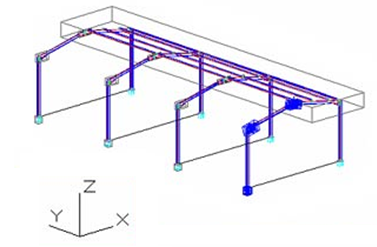
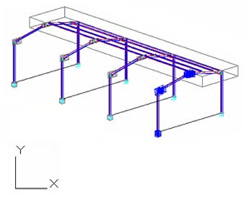
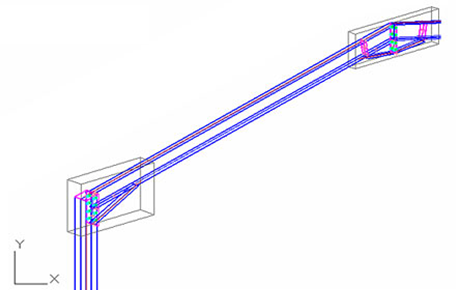
Rotate the model in the desired position you want to see the rafter beam in and change the UCS to View. The isometric view is UCS dependent and is created from the positive Z direction.
-
Open the Drawing Style Manager, select the drawing style you have modified and click Use. Select the rafter you want to detail.
Note: The model must be numbered before you create the drawing.
| UCS - View | |
|---|---|
|
|
| Model | Detail |
|---|---|
|
|