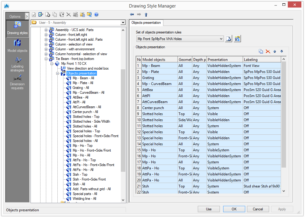
Object presentation rules determine the view content by defining how objects are displayed and labeled.
An object presentation rule assigns a specific method of displaying and labeling of model objects.
A model object acts as a filter for objects from the 3D model. It is defined by the type of Advance object, model role and an additional filter.
Example:
| Object type | Model role | Additional filter |
| Beam | Column | With holes |
The list of object presentation rules is available on the Objects presentation tab and is accessed by two methods:
- On the tree panel, select the Objects presentation branch
or
- On the View definition tab, in the "Object presentation and labeling" area, click Set
 .
.
The model objects are also displayed in the tree panel, under the Objects presentation branch.
Select a set of object presentation rules
Select a predefined set of object presentation rules from the list. The existing rules can be renamed and further definitions can be added.
| Button | Function |
|
|
Create a new set of object presentation rules. A copy of the current settings is created and a new item appears in the drop-down list. |
|
|
Rename a set of object presentation rules. The current settings are saved under a different name. |
Modify a set of object presentation rules
Modifications of the object presentation rules are performed using the four buttons on the right side of the "Objects presentation" area. All the views containing the modified set of object presentation rules are also changed.
| Button | Function |
|
|
Add a new object presentation rule |
|
|
Delete an object presentation rule |
Add a new object presentation rule
A new object presentation rule is created using an existing rule.
- Select an object presentation rule to use as a template.
- Click Add
 .
.
The new rule is added to the set of object presentation rules.
Delete an object presentation rule
- 1Select an object presentation rule to delete.
- 2Click Delete
 to delete the rule from the list.
Change the order of the list
The order of the object presentation rule list is modified with the two arrow buttons, ![]() and
and ![]() .
.
In the assignment of the model object, a certain order must be maintained to achieve the required results. Generally, the list is processed from top to bottom. If a setting can be applied, it will be used. Otherwise, it will move to the next entry.
Modify an object presentation rule
Each objects presentation rule can be modified by defining the geometric restriction, depth position, presentation rule and labeling rule.
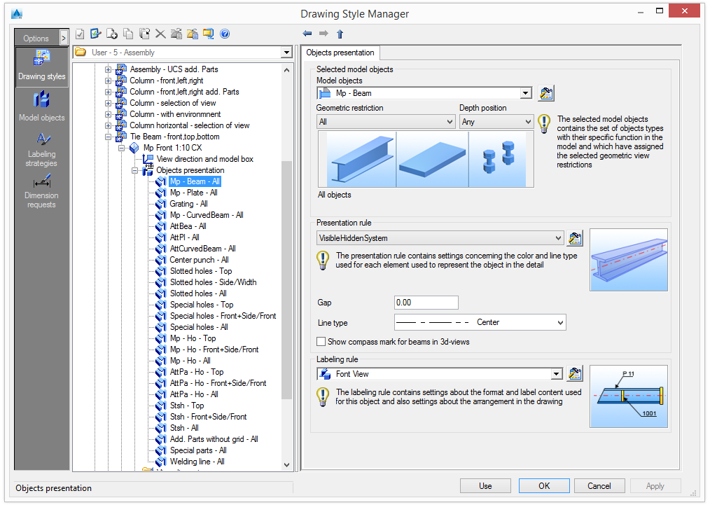
Set the view geometric restrictions for the selected model objects
Model objects are selected in the "Selected model objects" area.
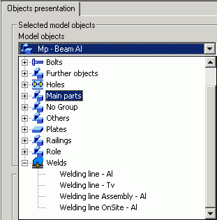
For details about the selected model objects, click Set ![]() . The model objects can be shared by different styles and can be managed separately as described in Model Objects.
. The model objects can be shared by different styles and can be managed separately as described in Model Objects.
The selected model objects define how they are seen in the detail. Two kinds of geometric view restrictions can be defined for each model object:
- Geometric restriction
- Depth position
The object presentation name is created by combining the name of the model object, the geometric restriction and the depth position.
Examples: Object presentation names
|
Column - Front |
The Column model object seen in detail from Front |
|
AttPlatesWithHoles-All-Rear |
Advance Plate objects that are attached to a main part and have holes in them, seen in detail from any direction and are placed "behind / under" the main part. |
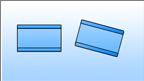
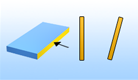
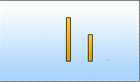
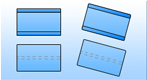
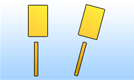
Geometric restriction
Defines the object view direction.
Example: The beam is seen in detail from Front and the plates are seen from their Side .
| Geometric restriction | Beams | Plates | Connecting elements |
|
All |
All model objects |
||
|
Front/Length |
The beams seen from the front view |
The plates seen from their length |
|
|
Front+Side/Front |

The beams seen from the front view or side view |

The plates seen from the front |

The bolts seen from the front |
|
Li Fr |
The beams aligned with XY directions, seen from the front view |
The plates seen from the front or side and linear |
|
|
Li Side |

The beams seen from the side view |
|
|
|
Li top |
|

|
|
|
Elements aligned with XY directions seen from the top |
|||
|
Linear |

|

|

|
|
Elements aligned with the detail XY directions |
|||
|
N-Li Fr |
|

|
|
|
Elements not aligned with the detail XY directions seen from the front |
|||
|
N-Li Side |
|

|
|
|
Beams seen from the side and not aligned with XY directions |
Plates and other elements seen from the side and not aligned with XY directions |
||
|
N-Li Top |
|

|
|
|
Elements seen from the top and non-linear |
|||
|
NotLinear |

|

|

|
|
Objects that are seen not aligned with the detail view XY directions |
|||
|
Side/Width |

The beams seen from their side |
Plates seen from their width |
|
|
Top |

Objects that are seen from the element top direction |

|

|
|
Top+Front/Length |
The beams seen from the top or front view |
The plates seen from the top or their length |
|
|
Top+Side/Width |
The beams seen from the top or side views |
The plates seen from the top or their width |
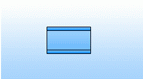
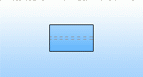
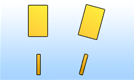
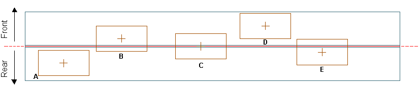
Depth position
The depth position is the "Z" position of the object relative to the main object of the detail. The following options are available:
| Depth position | Description |
|
Any |
On any side of the element |
|
Both sides |
On both sides (front and rear) of the main element (plates B, C, E) |
|
Both sides-Center |
(plate C) |
|
Both sides-CenterFront |
The attached element is on both sides (front and rear) but the center is in the front side of the main part (plate B) |
|
Both sides-CenterRear |
The attached element is on both sides (front and rear) but the center is in the rear side of the main part (plate E) |
|
Front (by center) |
The center of the attached element is in the front side of the main part (plates B, D) |
|
Front (entirely) |
The entire attached element is in the front side of the main part (plate D) |
|
Rear (by center) |
The center of the attached element is in the front side of the main part (plates A, E) |
|
Rear (entirely) |
The center of the attached element is on the rear side of the main part (plate A) |
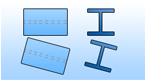
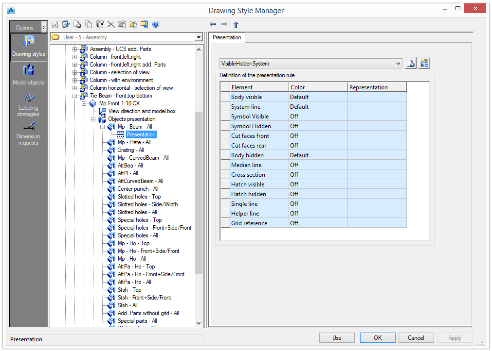
Set the presentation rule
The presentation rule contains settings for color and line type used for each object representation in the detail.
- In the "Presentation rule" area, select a presentation rule from the list.
- Click Set to view the definition of the selected presentation rule.
| Element | Representation |
|
Body visible |
Visible solid lines |
|
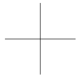
Axis |
Only the axes are visible |
|
Symbols |
Symbols |
|
Cut faces |
Sections plane of solids with model box |
|
Body hidden |
Hidden lines |
|
Median line |
Median (center) line of the object |
|
Cross section |
The cross section of the object |
|
Hatch |
The holes are hatched |
|
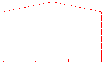
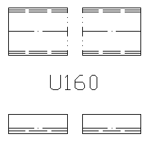
Simplified line |
The beams are shown only with a simplified line |
In the case of a simplified line, the line type and the gap are taken into account.
Examples:
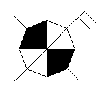
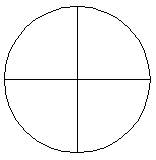
| Objects | Body visible | Axis | Symbols | Body hidden |
|
Bolts |

|
|
|
|
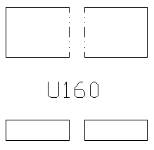
|
Holes |
|
|||
|
Beams |
|
|
|
Set the labeling rule
The labeling rule contains settings for content, layout and arrangement of a label.
- In the "Labeling rule" area, select a labeling rule from the list.
- Click Set to modify the selected rule. The labeling rules can be shared by different styles and can be managed separately as described in Labeling Strategies.