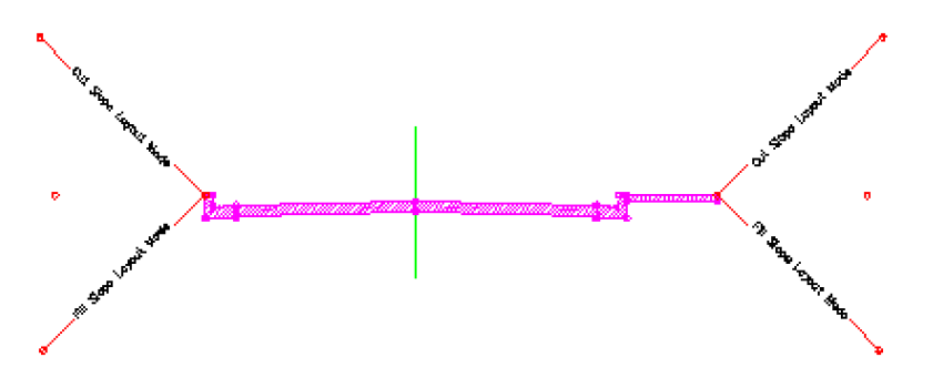
Assembly objects contain and manage a collection of subassemblies that are used to form the basic structure of a 3D corridor model.
An assembly is an AutoCAD Civil 3D drawing object (AECCAssembly) that manages a collection of subassembly objects. Together, assemblies and subassemblies function as the basic building blocks of a roadway or other alignment-based design. An assembly object must be applied along an alignment to form a corridor, and it can reference one or more offsets.

Adding one or more subassembly objects, such as travel lanes, curbs, and side slopes, to an assembly baseline creates an assembly object. This forms the design for a corridor section. The subassemblies are provided in a set of catalogs.

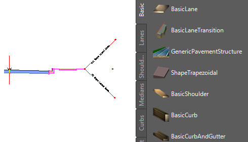
Roadway assembly (left), with subassemblies shown in a tool palette (right)
The following illustration shows a simple assembly object that represents one side (lane) of a two-lane road. Subassembly objects named BasicLane and BasicCurbAndGutter have been added to a baseline alignment, forming a single travel lane with a curb and gutter.

It is also possible to create more advanced assemblies referred to as conditional assemblies. A conditional assembly contains one or more conditional subassemblies, which apply subsequent subassemblies when specified conditions at a given station are met.
The following components comprise an assembly object:
- Insertion Point. This is the initial point in the drawing that is selected to create the assembly object. It corresponds to the centerline of the eventual corridor object. This is also known as the ground reference point and typically follows an alignment as well as a design profile (vertical alignment).
- Baseline. The baseline of an assembly typically displays as a visual aid (marker) representing a vertical axis at the assembly baseline point. If you want to attach a subassembly to the baseline point, you can do so by selecting the baseline marker. This method of attaching subassemblies to an assembly is sometimes easier than selecting the baseline point, especially when there are already one or more subassemblies attached at that point.
- Baseline Point. This is a point on the assembly typically representing the start point of the first subassembly that is attached to the assembly near the controlling alignment. By default, the baseline point coincides with the insertion point and therefore follows the centerline alignment and profile. If you want to begin sectional elements oriented away (horizontally and vertically) from the centerline, do so by moving this baseline point away from the assembly insertion point.
- Offset Line. The offset line is a typically vertical line visually representing a vertical axis at the offset point. If you want to attach a subassembly at an offset point, you can do so by selecting the offset line marker instead of selecting the offset point. This method of attaching subassemblies to an assembly offset point is sometimes easier than selecting the offset point, especially when there are already one or more subassemblies attached at that point.
- Offset Point. This is a point on the assembly representing the ground reference point along an offset alignment for the eventual corridor object. Subassemblies attached at this point follow an offset alignment and its designed profile. For example, in the case of a highway with service roads on one or both sides, the service road centerlines are represented by offset points. There is always just one baseline point on an assembly, and there can be zero or many offset points on an assembly. Offset points can be added to or deleted from an assembly at any time.
To complete the definition of an assembly object, you typically add multiple subassembly objects, such as lanes, curbs, or ditches, along an alignment. Each subassembly can connect to the assembly baseline point, any assembly offset point, or to another subassembly already associated with the assembly. A subassembly can also be attached to these points with a relative offset and/or elevation from the point.
After creating assembly objects, you can proceed with other corridor modeling tasks, such as creating corridor objects, feature lines, and section views.
Review the assemblies and corridors tutorials for step-by-step instructions on how to create a variety of assemblies for corridor model.
![]() Tutorial Exercise: Creating an Assembly
Tutorial Exercise: Creating an Assembly
![]() Tutorial Exercise: Creating an Assembly with a Transition Lane
Tutorial Exercise: Creating an Assembly with a Transition Lane