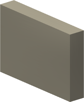
The following procedure describes the steps necessary to create an asset with variants. The asset example used is a simple rectangle that is 600 mm long, 400 mm wide, and 100 mm thick. Four asset variants are defined that produce lengths of 600 mm, 800 mm, 1000 mm, and 1200 mm.
- Create the asset.
- Define the user parameter(s) that drive the variants.
- Use Asset Builder to specify the landing surface, asset properties, optional insertion points, connectors, a descriptor, define the variants, and publish the asset. (In this procedure, only the landing surface and variants are defined.)
- Place the asset variants into a factory layout.
Create the asset
- Start by creating the part or assembly to be used as the asset. There are two methods that can be used.
- If you have an existing part or assembly, click
Factory tab
 Factory Launch panel
Import Model
Factory Launch panel
Import Model
 from the
  Create Asset drop-down menu. Open the existing part or assembly.
 - If you are starting from scratch, click
Factory tab
Factory Launch panel
Model as Part
 from the Create Asset drop-down menu. Enter the Sketch environment and build the asset.
If you wish to follow along with this procedure, use step 3 above. Be sure to use the metric Standard (mm) part template. If your template settings (as defined in the Factory Options dialog box) specify English units, then use the New command from the  Inventor Application menu and select the Standard (mm) part template.
- Once the metric template is open, create a 2D sketch.
- Select the XY plane on the Origin planes.
- Use the Two Point Center Rectangle command to create the rectangle. This command option ensures that the rectangle is centered on, and constrained to, the XY axes.
- Select the sketch origin as the center point and specify the length as 600 mm and the width as 400 mm.
- Finish the 2D sketch.
- Next, extrude the rectangle 100 mm in the positive Z direction.
- Save the part with the name metric variation.
Define the parameters
Once the part is complete, one or more User Parameters must be defined.
 On the ribbon, click
Factory tab
Parameters panel
Parameters
.
On the ribbon, click
Factory tab
Parameters panel
Parameters
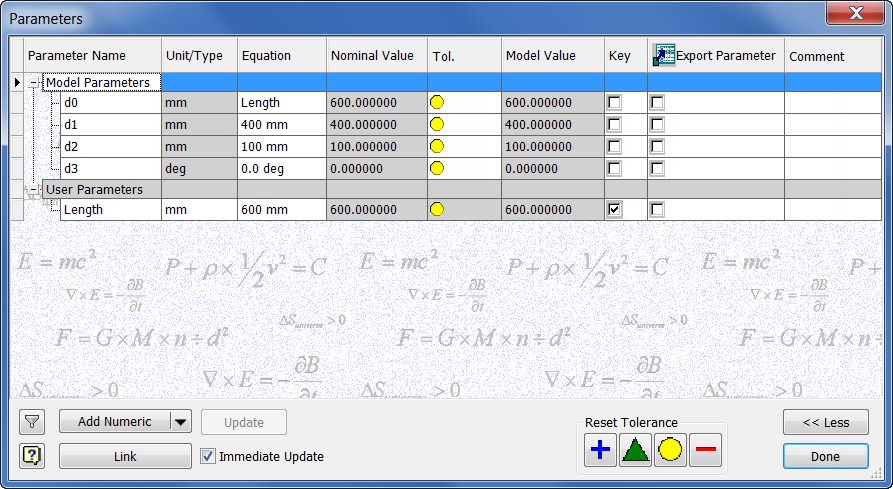
. - The Parameters dialog box is displayed.
- Observe that the length, width, and thickness dimensions are represented by the d0, d1, and d2 Model Parameters, respectively.
- You must now create a User Parameter. Click the Add Numeric button at the lower-left of the dialog box.
- Enter the name Length for the user parameter.
- Click inside the Unit/Type field, and then click OK to accept mm as the Unit Specification in the Unit Type dialog box.
- Enter 600 mm in the Equation field.
- In the d0 Equation field, replace 600 mm with Length.
- Finally, activate the Key parameter check box at the lower-right of the dialog box. This step is very important as it is this parameter that will drive the asset variants.
- When you have finished, your dialog box should appear as shown.
- Click Done to close the Parameters dialog box.
Define the asset variants
Do the following to define asset variants:
- Click
Create Asset tab
Factory Assets panel
Asset Builder
 .
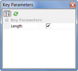
. - The Key Parameters dialog box displays showing the Length key parameter previously defined. The check box to the right of the parameter name should be checked.
- Click
Asset Builder tab
Author panel
Landing Surface
 .
. - Select the bottom surface of the rectangle to specify the landing surface. Click OK to close the Landing Surface dialog box. Note: At this point in the asset building process, you can optionally specify one or more insertion points, define a connector, create and place a descriptor, and specify asset properties. These steps are omitted for this example.
- Next, click
Asset Builder tab
Author panel
Asset Variants
 .
. - The Asset Variants dialog box is displayed.
- Select Length [600 mm] from the Parameters list at the upper-left of the dialog box.
- Click the add button (>>) to add Length to the Columns list at the upper-right.
- Next, click the Add button
 to create the first variant in the table. The variant name appears as Variant_1 in the variant list and 600 mm appears in the Length column. Note: To remove a variant name from the table, click the Remove button
 .
. - Highlight the name Variant_1 and rename it Length_600.
- Add three more variants and rename them Length_800, Length_1000, and Length_1200. Set their values in the Length column to 800 mm, 1000 mm, and 1200 mm, respectively.
- When complete, the Assets Variants dialog box should appear as shown.
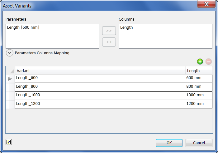
- Click OK when you are finished defining the asset variants.
Publish the asset
- Before publishing the asset, save metric variation.
- On the ribbon, click
Asset Builder tab
Publish panel
Publish Asset
 .
. - The Publish Asset dialog box displays.
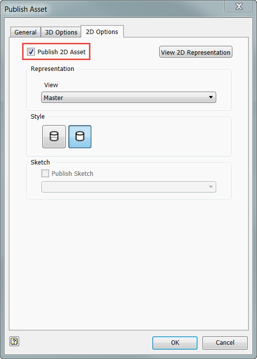
- Click the 2D Options tab and make sure that the Publish 2D Asset check box is enabled. This setting ensures that the asset gets published for use in AutoCAD Factory. Note: The Publish 2D Asset check box can also be enabled and disabled on the Asset Builder tab in the Factory Options dialog box. By default, this setting is enabled.
- Next, select the General tab and click the User Assets folder. (The asset variant is published in this folder for both Inventor Factory and AutoCAD Factory.)
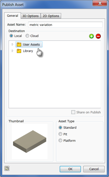
- Click the OK button to publish the asset and close the dialog box.
- The Publishing Asset…dialog appears with a progress meter as the asset is published. The dialog closes automatically when publishing is complete.
-
 On the ribbon, click
Asset Builder tab
Exit panel
Finish Asset Builder
.
On the ribbon, click
Asset Builder tab
Exit panel
Finish Asset Builder
.
Place the assets in Inventor Factory
- Begin a new factory layout using the Factory Layout (mm).iam template.
If your template settings (as defined in the Factory Options dialog box) specify English units, then use the New command from the
Inventor Application menu and select the Factory Layout (mm).iam template. - In the Assets Browser, double-click to open the User Assets folder.
- The metric variation asset appears with an icon at the upper-left denoting that there are four variants of this asset.
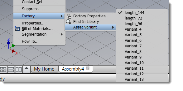
- Right-click over metric variation to display the pop-up context menu. Observe the four defined variants in the Asset Variant submenu.
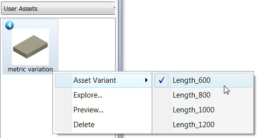
- Select Length_600 from the submenu and place the asset on the factory floor as you would any asset. Leave the rotation angle at 0 degrees.
- Repeat the procedure for the three remaining variants.
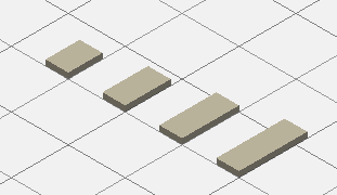
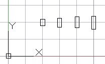
- After placing the four variants, the factory layout will appear similar to the following illustration.
As an experiment, begin a new metric drawing in AutoCAD Factory. Place each variant into the 2D factory layout using the same procedure as you would in a 3D layout. The illustration shows the asset variants as they appear in AutoCAD Factory.
Replacing an asset variant in the layout
Once an asset variant is placed in a layout (whether in AutoCAD Factory or Inventor Factory), it can easily be replaced with a different variation.
- Select (left-click) the asset variant in the AutoCAD or Inventor layout that you wish to replace.
- Next, right-click to display the pop-up context menu.
- Select Factory > Asset Variant, and then select the replacement variant from the submenu.
Using iLogic rules with Asset Variants
There are several things to consider when using iLogic rules with asset variant parameters.
- For an asset, place any iLogic rules ensuring valid parameter values (e.g. setting minimum or maximum values of a parameter) at the top of the list of iLogic rules in the iLogic browser. The order of the rules is important when parameter values get changed in Inventor Factory because multiple parameters are changed simultaneously and then the iLogic rules get run once.
- If an asset is using iLogic rules to define some parameter relationships, then the asset creator needs to consider carefully whether to use those parameters as variant parameters. If the iLogic rules are defining the parameter relationships, then the values of the parameters in question for any variant will be overridden by the iLogic rules.
- When creating an asset variant, make sure that the specified variant parameter values will actually be used in the asset and NOT overridden by iLogic rules. This verification can be achieved by manually changing the parameter values in the Parameters dialog box to match the variant parameter values and then making sure the specified values are not overridden.
As an example, assume that an asset is created with the variants specified as shown in the following image:
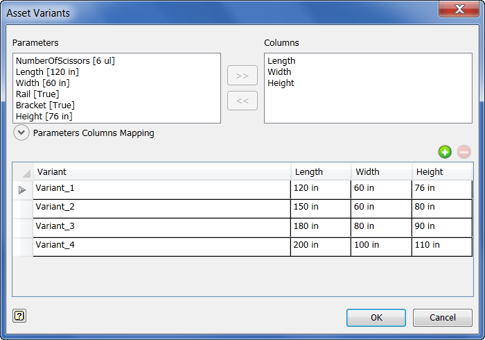
Now, change the specified variant parameters (Length, Width, and Height) of the asset to match the values specified for Variant_3 from the table above. (Keep in mind that some iLogic rules have been created governing parameter relationships as shown in the Parameters dialog box below). Changing the parameter values produces the following:
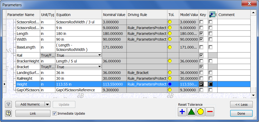
Notice that the Rule_ParametersProtect iLogic rule has overridden the specified variant parameters to produce the following discrepancies:
| Parameter | Specified value in Variant | Actual value in Model |
|---|---|---|
| Length | 180 in | 180 in |
| Width | 80 in | 90 in |
| Height | 90 in | 113.55 in |