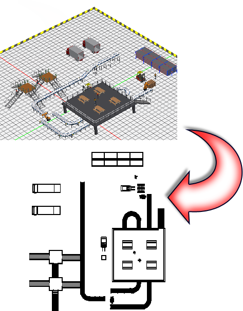
A 3D factory floor layout can be saved as an AutoCAD 2D drawing at any time using the Publish/Update DWG command. Once the drawing has been successfully published, you have the option to immediately launch AutoCAD and open the drawing in the AutoCAD graphics window.
The Publish/Update DWG command generates two drawing files. The first, 3dlayoutname_published.dwg, is the master containing external references (xrefs) of the underlying view and all DWG overlays. The second, 3dlayoutname_published_view.dwg, contains the 2D drawing view of the Inventor layout inserted into AutoCAD model space. For both drawings, 3dlayoutname is the name of the current factory layout. Both drawing files are saved in the same folder as the factory layout.
Publish/Update DWG
- Click Factory tab
 Layout panel Publish/Update DWG
 .
. - Two drawing files are created and saved in the same folder as the current factory layout. The first drawing, 3dlayoutname_published.dwg, is the master containing external references (xrefs) of the underlying view and all DWG overlays. The second drawing, 3dlayoutname_published_view.dwg, contains the 2D drawing view of the Inventor layout inserted into AutoCAD model space. For both drawings, 3dlayoutname is the name of the current factory layout. Note: The AutoCAD template file (.dwt) used for DWG creation is automatically selected based on the system of units in use. You can specify a different drawing template file on the Templates tab in the Factory Options dialog box.
- You are notified when the 3dlayoutname_published_view drawing has been published successfully, and prompted to open it in AutoCAD. Answer Yes or No as required.
- After AutoCAD opens, it may be necessary to perform a Zoom All or Zoom Extents operation to view the drawing.