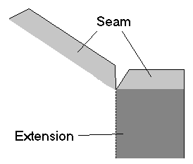
The Notches option allows the connectors that are used on rectangular ducts to be modified for the development of the ductwork that they are applied to. This is illustrated in the example below. Without the removal of the seam, the flange allowance could not be run through the same seaming procedure as the rest of the seam.

Creating Notches
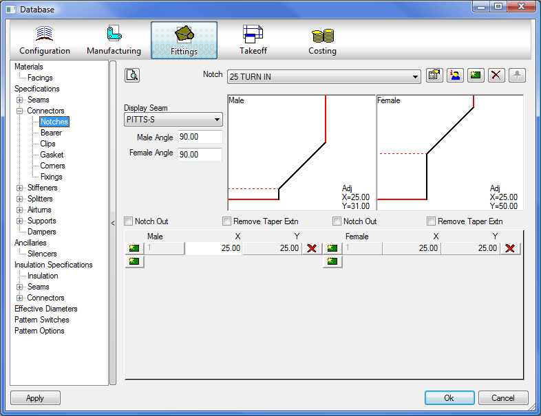
Notches cannot be applied to a development directly. To apply a notch you must first associate it with a connector. Notches are configured from the notches dialog in the pattern database.
Print / Print Preview Icon

Clicking on this button will preview the notch settings with an option to print them.
Display Seam
Allows the user to change the seam that is displayed in the notch preview windows. This does not have a direct effect on the notch, but is useful for visualising the notch when in the creation process. The list of seams is taken from the seam database.
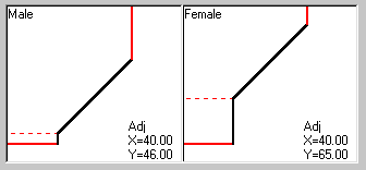
Male Angle
Sets the angle to which the male seam will be cut.
Female Angle .
Sets the angle to which the female seam will be cut
Notch (Pulldown Menu)

Displays a list of the currently configured notches. It is inadvisable to change any of the pre-defined notches if you are not sure where they are used. It is safer to create a new notch as there are no limits to the number of new notches creatable. To create a new notch:
- Click the
 icon to the right of the pulldown menu.
 - You will be asked if you want to copy the settings from the currently selected notch. If this notch is similar to the one you want to create click Yes. If you want to start from scratch, click No.
- The
 icon is used if you want to delete a notch.
 - The
 Icon is used to add notches to the database which have been brought in with other items, if this is applicable then the icon will be in color.
Automated Functions
There are two options to assist in the creation of the notch. These options allow the most common notches to be applied without specifying actual sizes. These settings are Notch Out and Remove Taper Extensions. Both of these settings have separate male and female settings so that they can be applied to the correct developments.
Notch Out
This removes the material where the seam and connector allowances meet.
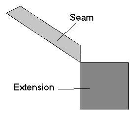
Remove Taper Extensions
As it is quite common that a part cannot be turned while seaming, it is neceA BR tag was used here in the original source.ssary to remove any material that might catch during the process, or at least limit the effect. An example of this is the taper fitting.
Notch Definition The boxes below the Notch Out and Remove Taper Extension checkboxes can then be used to enter the dimensions of the notch. To create a typical notch follow the example below.
- Click on the icon to the right of the Notch pulldown menu.
- You should receive a prompt asking whether you wish to make a copy of the existing notch, click No.
- Give the notch a different name to all the other notches in the list.
- Create a new set of entries under the Male column by clicking the icon on the left hand side of the male column.
- In the Male X box, type 40.
- In the same way, enter 40 in the Male Y box.
- Enter 40 for the Female X box.
- Enter 40 for the Female Y box.
- Select a seam to display with the notch by selecting PITTS-S from the Display Seam pulldown box.
- You should now have a notch which is ready for use in your job (for example, to be associated with a connector).
Note that in the above graphic the Y= lengths are both longer than the values you have entered in, in this case 40 for each. This is because it is adding the Y= allowance to the seam allowance, as defined under the seams tab.
- Click Apply followed by OK to save the changes to your database and exit the dialog.
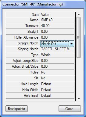
This can then be applied to a Connector using the Straight and Taper Notch fields.