Description:
The default CAM-Duct installation will be set to measure the radius of a bend, for example, to the outside of the fitting. However, in some instances, although the measurements to the center-line of the fitting may be known, it is not always possible to calculate the inside radius - for example, this could apply where insulation is being used. To cater for this instance, the Center Line Input option can be enabled checked for those patterns which have been designed to use this feature.
Enabling the Center Line Input option
By default, center line input is not enabled.
- Click Utilities > Item Folders or select the Item Folders icon from the Utility Bar.
- Select the Round folder.
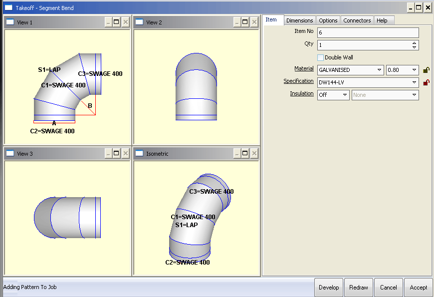
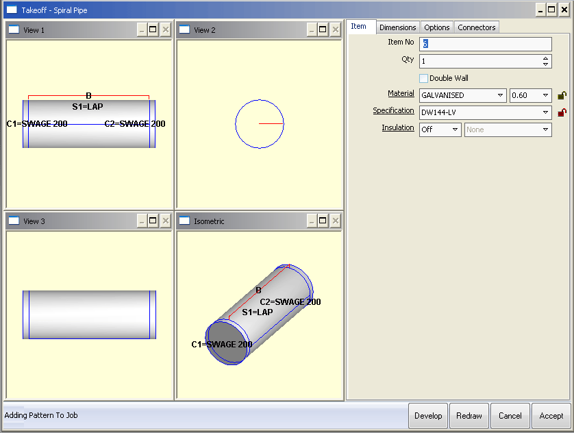
- Select the desired fitting, in this case the Segment Bend and click on the Item tab. The Takeoff screen will look similar to the one below.
- Click Takeoff > Customise and select the Item Information tab.
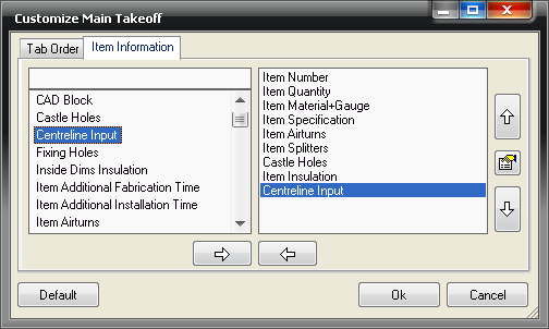
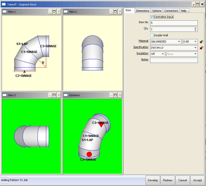
- The left hand pane of the screen details all of the possible item fields that could be enabled in the Item tab. Click on the Centerline Input option in the left hand pane.
- Click the right-pointing arrow. This will then copy the field across to the right hand pane, placing it at the top of the list.
- The position of the option within the right hand pane will determine where about within the Item tab the option is displayed . Click the downward-pointing arrow to move the field to its required position in the list. In this case, move the option to the bottom of the list. As in the image above.
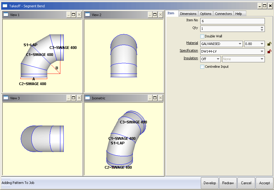
- Click OK to save the information, and instantly you will see the takeoff screen change to cater for this new field:
Using the Center Line Input option
Once the option has been enabled it is possible to start using it. Different patterns use this option in different ways. The following section illustrates this.
The Segment Bend Pattern
- Click on the Item tab and ensure that the Center Line Input option is not enabled.
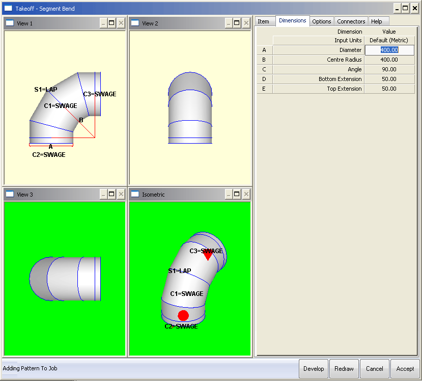
- Then, click on the Dimensions tab and note that the B Dimension asks for the Inner Radius.
- In the top-left view of the image below, the entered value of 200 defines the radius to the inside edge of the bend, as shown by the red lines.

- Click on the Item tab and enable the Center Line Input option.
- Click on the Dimensions tab and note that Dimension (B) now asks for the Center Radius, and the value has automatically changed to reflect that.
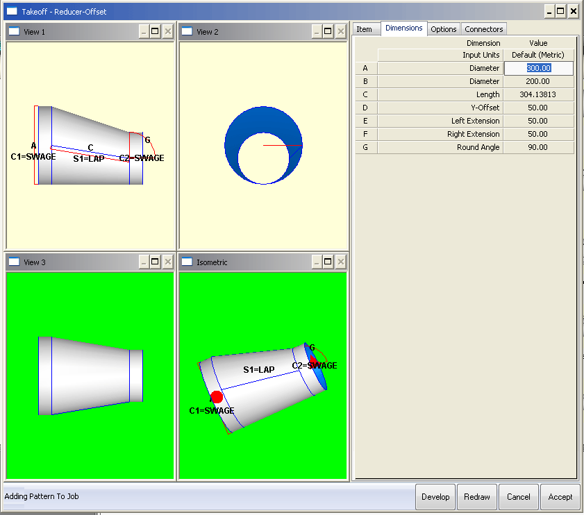
The Reducer (Offset T1) Pattern
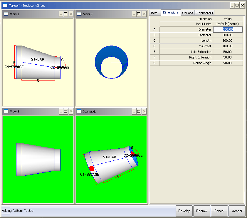
When using the Center Line Input option with this fitting, two fields are affected; the Length and the Offset.
- Click on the Item tab and ensure that the Center Line Input option is not enabled.
- Then, click on the Dimensions tab and enter the dimensions listed below. Paying careful attention to the length and offset entries.
- Click on the Item tab and enable the Center Line Input option.
- Click on the Dimensions tab and note that the Offset has changed from 100 to 50 and the Length has changed to 304.138.
- The two top images have also changed to reflect the changes.
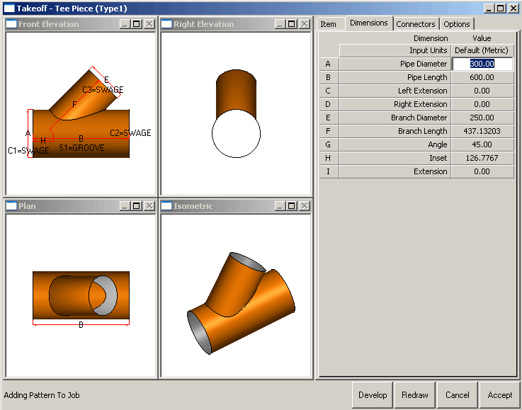
The Tee Piece Pattern
When using the Center Line Input option with this fitting, two fields are affected. The Branch Length and the Inset.
- Click on the Item tab and ensure that the Center Line Input option is not enabled.
- Then, click on the Dimensions tab and enter the dimensions listed below. Paying careful attention to the Branch Length and Inset entries.
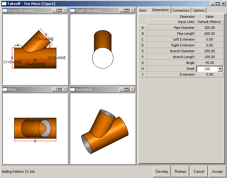
- Click on the Item tab and enable the Center Line Input option.
- Click on the Dimensions tab and note that the Branch Length has changed from 250 to 437.13203 and the Inset has changed to 126.7767.
- The two top images have also changed to reflect the changes.