You can enable the Stock check box on the Simulation dialog box to see the stock at the current toolpath position during simulation. This stock simulation uses an extremely fast simulation engine with full multi-core/CPU support which allows you to quickly see the stock as is looks at any given position. The engine is even fast enough to allow backwards stock simulation on newer workstations. You should generally see huge 3D programs exceeding 100Mb of NC code being simulated within seconds. The engine is only intended for 3D simulation and undercutting and indexed machining is not supported.
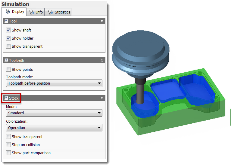
Simulating the stock
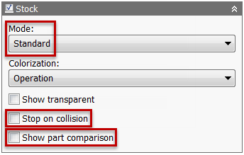
Advanced Stock Simulation Options
The Mode drop-down menu offers two options for the display of stock simulation.
- Standard - This mode supports simulation of any toolpath including 2D, 3-axis, 3-axis indexing (3+2), and multi-axis. It also supports undercutting and collision detection.
- Fast (3-axis only) - This optional simulation mode offers additional stock colorization options and more control over the display quality when simulating the stock removal results. It is significantly faster than Standard mode when working with large toolpaths, but is does not support 3-axis indexing, multi-axis, undercutting, or collision detection.
The Standard mode displays the Stop on collision and Show part comparison check boxes. Enable the Stop on collision check box to stop the stock simulation if a collision occurs between the shaft, holder, and fixture. Enable the Show part comparison check box to show stock and part comparison where red indicates a gouge of the part and blue indicates an excess of stock.
The Show part comparison option offers two additional parameters:
- Number of intervals: - Specifies the number of steps to use for the stock and part comparison color gradient.
- Interval: - Sets the distance between each step in the color gradient used for stock and part comparison.
Stock Colorization
The stock simulation allows you to colorize the stock according to several different machining criteria like up/down milling and cutting direction. This allows you to visualize potential machining problems before actually machining the part. Colorization of the stock often gives a quick and good overview of potential machining issues relevant for both part quality and cutting performance.
The Colorization: drop-down menu offers the following options:
- Use material - Selecting this option activates the Material: drop-down menu and displays the workpiece using the material selected from that drop-down.
- Operation - When selected, the software assigns a unique color to each operation being simulated. The color for each operation is displayed on the corresponding cutter path.
- Tool - This option assigns a unique color to each tool by tool number. The corresponding color is displayed on the cutter path.
- Movement - When selected, the color is determined by movement type (e.g. rapid, ramp, cutting, lead-in, lead-out). The movement type is displayed in the Position group on the Info tab of the Simulation dialog.
- Feedrate - With this option, each different cutting feedrate has a different color; with blue being the slowest feedrate and red being the fastest feedrate. As with Movement, the feedrate is displayed in the Position group on the Info tab of the Simulation dialog.
- Slope - When selected, the colorization for up/down milling uses the Z axis as reference. Positive milling (+Z) is in red, and negative milling (-Z) is in blue.
- Direction - This option sets the colorization of the cutting direction in the XY plane. Each different direction angle of cut has a different color.
- Type - When selected, colorization is based on the toolpath moves. There are different colors for linear, arc moves, and clashes.
- Flow - This option colorizes toolpath portions that share the same movement (e.g. start of the flow is blue and end of the flow is red).
- Climb/Conventional - When selected, the cutter paths for climb milling are shown in red while conventional milling cutter paths are shown in blue.
- Engagement angle - With this option, color is based on the angle of the tool perimeter that is in contact with the workpiece. The angle is measured in a plane perpendicular to the tool axis. Example: When the tool is fully engaged, the engagement angle is 180 degrees but half of the angle is displayed in red (climb milling), and the other half is displayed in blue (conventional milling).
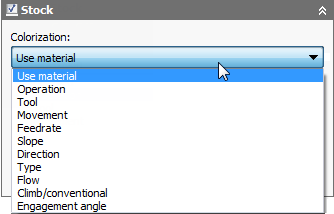
The Colorization: drop-down menu options. Selecting the Use material option activates the Material: drop-down menu.
In the image shown below, the machining direction of the offset passes to either side of the pencil pass are clearly shown in different colors; indicating opposite machining directions which can degrade part quality. The toolpath of interest would be indicated by abrupt changes in color.
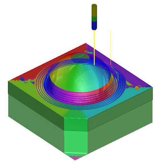
Transparent stock colored by Direction for an adaptive and pencil toolpath
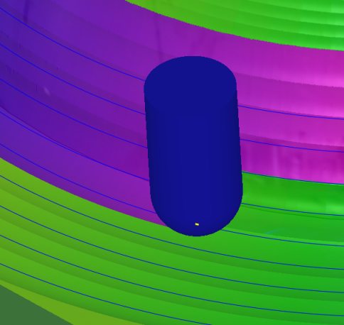
Stock colorization close-up
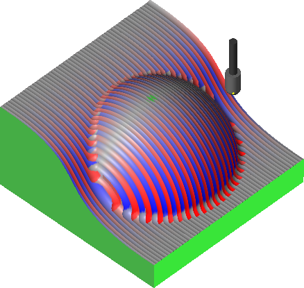
Colorization by Slope showing up and down milling as blue and red, respectively
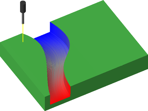
Colorization by Flow