You can control the machining area by depth for most machining strategies on the Heights tab. The machining area is defined by the Top Height and Bottom Height. On the Heights tab, you can also control the retracts by setting the Clearance Height, Retract Height, and Feed Height.. Each height is defined by an offset amount and a mode that tells from which other height the offset applies. The absolute heights are always in relation to the operation origin which defaults to the WCS defined in the setup.
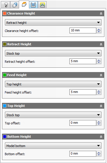
The Heights tab
The currently selected height is automatically previewed as shown in the image below. The plane dimensions are derived from the bounding box of the selected geometry.
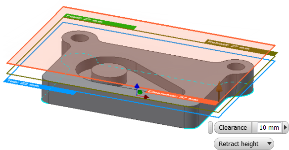
Top plane preview
Each height (level), supports a subset of the following modes:
- Retract height
- Feed height
- Top height
- Bottom height
- Model top
- Model bottom
- Stock top
- Stock bottom
- Selected contour(s)
- Selection
- Origin (absolute)
Each of these modes puts the associated height in a relative mode where the height is in relation to the selected height.
As an example, if you select Retract height in the Clearance Height drop-down list and the clearance height offset is 5 mm, the actual clearance height will be 5 mm above the retract height.
- Model top / Model bottom
These modes set the associated height relative to the extents of selected model.
- Stock top / Stock bottom
These modes set the associated height relative to the extents of the stock defined in the setup.
-
Selected contour(s)
When using this option, the height is relative to the selected contour(s).
-
Selection
Choosing this option provides a selection field that allows you to pick any point/vertex, sketch segment, edge, or face on the model.
-
Origin (absolute)
Choosing Origin (absolute) allows you to manually control the associated height by entering a fixed value in relation to the operation origin.
All height modes are fully associative such that the heights update automatically when the model and stock changes.
The heights can be set relative to any selectable point, edge, or face on the model by using the Selection setting. As a shortcut to setting a height from an element, it is not necessary to choose Selection first. Instead, just move focus to the height you wish to set by clicking on the height offset field and then pick an element on the model.
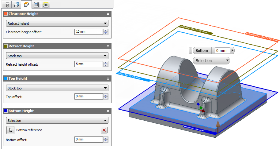
Picking a face on the model as the bottom height for a Contour finishing strategy
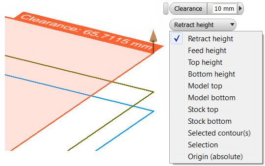
The Heights Mini-Toolbar
As an alternative to setting heights on the Heights tab, you can also select a height plane in the graphics window and then, using the mini-toolbar, choose the desired height relative to another and enter the offset value.
To use the mini-toolbar, do the following:
- Click the Heights tab in the Operation dialog box.
Each of the selectable height planes appear in the graphics window. The Clearance Height is orange, the Retract Height is olive green, the Feed Height is green, the Top Height is light blue, and the Bottom Height is dark blue.
- Click the height plane you wish to set. The mini-toolbar displays near your cursor position. In the example shown above, the Clearance Height has been selected.
- Use the drop-down list to select the height to which the selected height plane is to be set relative.
- Enter the required offset value in the mini-toolbar's numeric field, or dynamically drag the arrow manipulator to the desired height.
- Click the OK button on the Heights tab to set the height and complete the operation.