|
Access: |
Ribbon:
CAM tab
 Turning panel
Part
Turning panel
Part

|
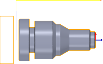
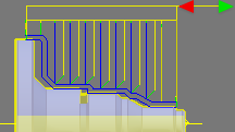
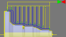
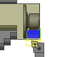
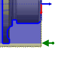
The Part strategy is used for cutting off the part for machining on another spindle, or when the part has been fully machined.
 Tool tab settings
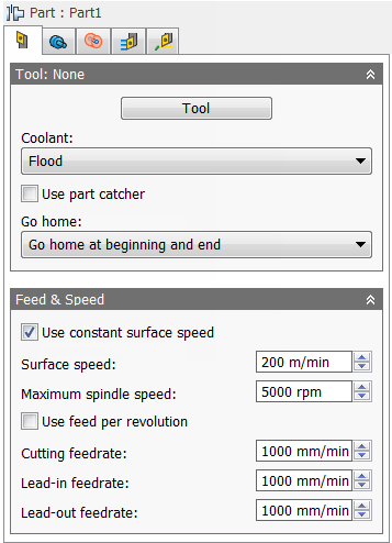
Coolant:
The type of coolant used with the tool.
Use part catcher
Enable to activate the part catcher when available.
Go home:
The Home position is a known Z value relative to the WCS and is defined within the Work Coordinate System (WCS) section on the Setup tab of the Setup strategy dialog.
You can force the tool to move to the Home position prior to starting the operation, or once the operation has finished. The tool will always pull out of the stock in the X axis until it reaches the Clearance height, then move to the Home position in the Z.
-
Don't go home
Don't Go Home
-
Go home at beginning
Go Home At Beginning
-
Go home at end
Go Home At End
-
Go home at beginning and end
Go Home At Beginning And End
Use constant surface speed
Enable to automatically adjust the spindle speed to maintain a constant surface speed between the tool and the workpiece as the cutting diameter changes . Constant Surface Speed (CSS) is specified using G96 on most machines.
Spindle speed:
The rotational speed of the spindle.
Surface speed:
The spindle speed expressed as the speed of the tool on the surface.
Maximum spindle speed:
Specifies the maximum allowed spindle speed when using Constant Surface Speed (CSS).
Use feed per revolution
Enable to automatically adjust the feedrate based on the RPM of the spindle to maintain a constant chip speed.
Cutting feedrate:
Feed used in cutting moves.
Lead-in feedrate:
Feed used when leading in to a cutting move.
Lead-out feedrate:
Feed used when leading out from a cutting move.
 Geometry tab settings
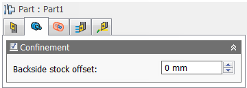
Confinement
Toolpaths can be contained within a specific region using the Confinement button to select confinement boundaries. Confinement regions can be defined with a combination of edges, surfaces, or sketch points.
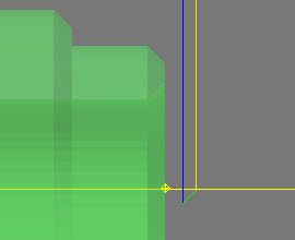
Backside stock offset:
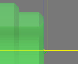
Specifies the distance to machine beyond the backside of the model.
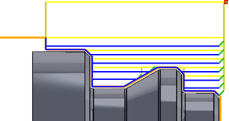
Negative Backside Offset

Positive Backside Offset
 Radii tab settings
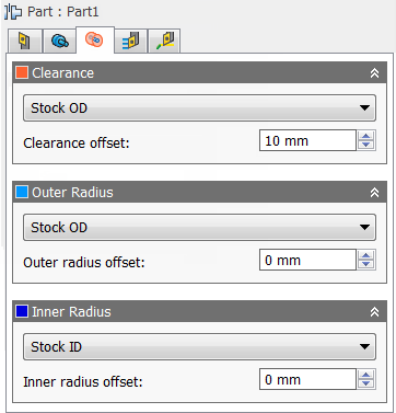
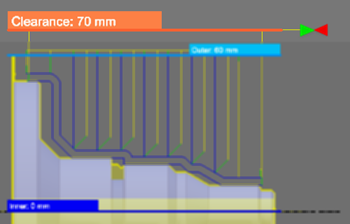
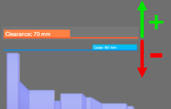
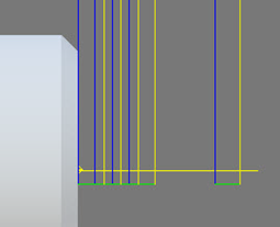
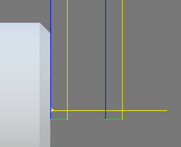
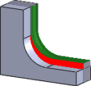
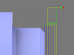
Clearance
Set this height to control the radius where the tool enters and exits the toolpath. The tool approaches and retracts from inside the stock along the Z axis (spindle axis) at this radial clearance offset. The value displayed on the orange tab represents its current radius relative to the setup axis.
Outer Clearance Radius
- Stock OD- Sets the clearance radius to match the radial extremities of the stock defined in the setup.
- Model OD - Sets the clearance radius to match the outer radial extremities of the model as defined in the setup.
- Outer radius - Choosing this option allows you to offset the clearance radius from the Outer radius. However, the clearance radius must be larger than the Outer radius, so a positive value must be entered in the Clearance offset field.
- Inner radius - Using this option in combination with the Clearance offset value allows you to drive the Clearance radius from the innermost location where tool paths are generated. This is a useful method for containing toolpath depth in certain scenarios. Make sure the clearance radius results in the tool clearing all remaining stock. This can be verified by running stock simulation.
- Model ID - Using this option in combination with the Clearance offset value allows to you to drive the Clearance radius from the smallest diameter of the defined stock. Make sure the clearance radius results in the tool clearing all remaining stock. This can be verified by running stock simulation.
- Stock ID - Using this option in combination with the Clearance offset value allows to you to drive the Clearance radius from the smallest diameter of the defined stock. Make sure the clearance radius results in the tool clearing all remaining stock. This can be verified by running stock simulation.
- Selection - Select any face, vertex, or point on the model to define the Clearance radius.
- Radius - This option allows you to enter a radius value in the Clearance offset field.
- Diameter - This option allows you to enter a diameter value in the Clearance offset field.
Clearance offset:
Specifies the clearance offset value.
Outer Clearance Offset
Outer Radius
Defines the radial confinement by limiting the outer radial range of the toolpath. You can choose from the following:
Outer Radius
- Stock OD
- Model OD
- Inner limit
- Model ID
- Stock ID
- Selection
- Radius
- Diameter
Outer radius offset:
Specifies the outer radius offset value.
Inner Radius
Defines the radial confinement by limiting the inner radial range of the toolpath. You can choose from the following:
Inner Radius
- Stock OD
- Model OD
- Outer limit
- Model ID
- Stock ID
- Selection
- Radius
- Diameter
Inner radius offset:
Specifies the inner radius offset value.
 Passes tab settings
Tolerance:
The machining tolerance is the sum of the tolerances used for toolpath generation and geometry triangulation. Any additional filtering tolerances must be added to this tolerance to get the total tolerance.
Loose Tolerance .100
Tight Tolerance .001
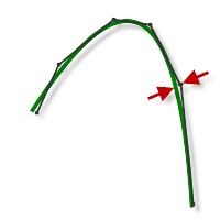
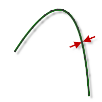
CNC machine contouring motion is controlled using line G1 and arc G2 G3 commands. To accommodate this, CAM approximates spline and surface toolpaths by linearizing them; creating many short line segments to approximate the desired shape. How accurately the toolpath matches the desired shape depends largely on the number of lines used. More lines result in a toolpath that more closely approximates the nominal shape of the spline or surface.
Data Starving
It is tempting to always use very tight tolerances, but there are trade-offs including longer toolpath calculation times, large G-code files, and very short line moves. The first two are not much of a problem because Inventor HSM calculates very quickly and most modern controls have at least 1MB of RAM. However, short line moves, coupled with high feedrates, may result in a phenomenon known as data starving.
Data starving occurs when the control becomes so overwhelmed with data that it cannot keep up. CNC controls can only process a finite number of lines of code (blocks) per second. That can be as few as 40 blocks/second on older machines and 1,000 blocks/second or more on a newer machine like the Haas Automation control. Short line moves and high feedrates can force the processing rate beyond what the control can handle. When that happens, the machine must pause after each move and wait for the next servo command from the control.
Transfer stock
Specifies that the stock should be clamped for use on the other spindle.
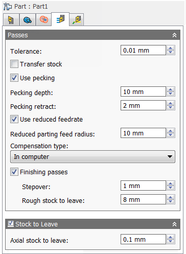
Use pecking
Enable to activate pecking options.
Pecking depth:
Specifies the pecking depth.
Pecking retract:
Specifies the pecking retract amount.
Use reduced feedrate
Enable to reduce the feed when parting.
Reduced parting feed radius:
Specifies the radius at which to reduce the feedrate when parting.
Compensation type:
Specifies the compensation type.
- In computer - Tool compensation is calculated automatically by Inventor HSM, based on the selected tool diameter. The post-processed output contains the compensated path directly, instead of G41/G42 codes.
- In control - Tool compensation is not calculated, but rather G41/G42 codes are output to allow the operator to set the compensation amount and wear on the machine tool control.
- Wear - Works as if In computer was selected, but also outputs the G41/G42 codes. This lets the machine tool operator adjust for tool wear at the machine tool control by entering the difference in tool size as a negative number.
- Inverse wear - Identical to the Wear option, except that the wear adjustment is entered as a positive number.
Finishing passes
Enable to perform finishing passes using the side of the tool.
Finishing passes on
Finishing passes off
Stepover:
The maximum distance between finishing passes.
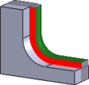
Rough stock to leave:
Specifies the amount of radial stock to leave for the roughing pass.
Stock to Leave
Positive
Positive Stock to Leave - The amount of stock left after an operation to be removed by subsequent roughing or finishing operations. For roughing operations, the default is to leave a small amount of material.
None
No Stock to Leave - Remove all excess material up to the selected geometry.

Negative
Negative Stock to Leave - Removes material beyond the part surface or boundary.
Axial (floor) stock to leave:
The Axial stock to leave parameter controls the amount of material to leave in the axial (along the Z-axis) direction, i.e. at the end of the tool.
Axial stock to leave
Both radial and axial stock to leave
Specifying a positive axial stock to leave results in material being left on the shallow areas of the part.
For surfaces that are not exactly horizontal, Inventor HSM interpolates between the axial and radial (wall) stock to leave values, so the stock left in the axial direction on these surfaces might be different from the specified value depending on surface slope and the radial stock to leave value.
Changing the radial stock to leave automatically sets the axial stock to leave to the same amount, unless you manually enter the axial stock to leave.
For finishing operations, the default value is 0 mm / 0 in, i.e. no material is left.
For roughing operations, the default is to leave a small amount of material that can then be removed later by one or more finishing operations.
Negative stock to leave
When using a negative stock to leave the machining operation removes more material from your stock than your model shape. This can be used to machine electrodes with a spark gap, where the size of the spark gap is equal to the negative stock to leave.
Both the radial and axial stock to leave can be negative numbers. However, when using a ball or radius cutter with a negative radial stock to leave that is greater than the corner radius, the negative axial stock to leave must be less than or equal to the corner radius.
 Linking tab settings
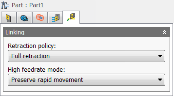
Retraction policy:
Controls how the tool should retract to the clearance diameter after every cutting pass. or just retract a short distance away from the job. The distance is determined by the Safe Distance value.
-
Full retraction - completely retracts the tool to the
Retract Height at the end of the pass before moving above the start of the next pass.
Full retraction
-
Minimum retraction - moves straight up to the lowest height where the tool clears the workpiece, plus any specified safe distance.
Minimum retraction
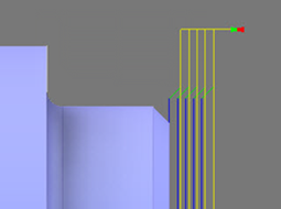
High feedrate mode:
Specifies when rapid movements should be output as true rapids (G0) and when they should be output as high feedrate movements (G1).
- Preserve rapid movement - All rapid movements are preserved.
- Preserve axial and radial rapid movement - Rapid movements moving only horizontally (radial) or vertically (axial) are output as true rapids.
- Preserve axial rapid movement - Only rapid movements moving vertically.
- Preserve radial rapid movement - Only rapid movements moving horizontally.
- Preserve single axis rapid movement - Only rapid movements moving in one axis (X, Y or Z).
- Always use high feed - Outputs rapid movements as (high feed moves) G01 moves instead of rapid movements (G0).
This parameter is usually set to avoid collisions at rapids on machines which perform "dog-leg" movements at rapid.
High feedrate:
The feedrate to use for rapids movements output as G1 instead of G0.