|
Access: |
Ribbon:
CAM tab
 2D Milling panel
2D Adaptive
2D Milling panel
2D Adaptive

|
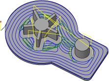
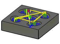
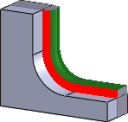
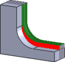
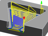
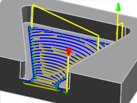
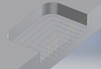
An Adaptive Clearing strategy creates a toolpath from chained contours rather than surfaces or solids. It is possible to define a taper angle for the walls.
 Tool tab settings
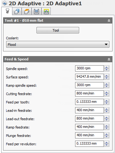
Coolant:
The type of coolant used with the tool.
Spindle speed:
The rotational speed of the spindle.
Surface speed:
The spindle speed expressed as the speed of the tool on the surface.
Ramp spindle speed:
The rotational speed of the spindle when performing ramp movements.
Cutting feedrate:
Feed used in cutting moves.
Feed per tooth:
The cutting feedrate expressed as the feed per tooth.
Lead-in feedrate
Feed used when leading in to a cutting move.
Lead-out feedrate:
Feed used when leading out from a cutting move.
Ramp feedrate:
Feed used when doing helical ramps into stock.
Plunge feedrate:
Feed used when plunging into stock.
Feed per revolution:
The plunge feedrate expressed as the feed per revolution.
 Geometry tab settings
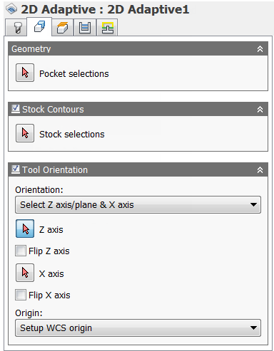
Stock Contours
Enable to specify the perimeter of the stock that needs to be faced.
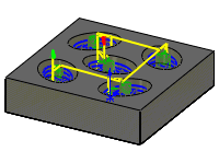
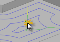
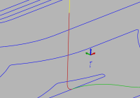
Tool Orientation
Specifies how the tool orientation is determined using a combination of triad orientation and origin options.
The Orientation drop-down menu provides the following options to set the orientation of the X, Y, and Z triad axes:
- Setup WCS orientation - Uses the workpiece coordinate system (WCS) of the current setup for the tool orientation.
- Model orientation - Uses the coordinate system (WCS) of the current part for the tool orientation.
- Select Z axis/plane & X axis - Select a face or an edge to define the Z axis and another face or edge to define the X axis. Both the Z and X axes can be flipped 180 degrees.
- Select Z axis/plane & Y axis - Select a face or an edge to define the Z axis and another face or edge to define the Y axis. Both the Z and Y axes can be flipped 180 degrees.
- Select X & Y axes - Select a face or an edge to define the X axis and another face or edge to define the Y axis. Both the X and Y axes can be flipped 180 degrees.
- Select coordinate system - Sets a specific tool orientation for this operation from an Inventor User Coordinate System (UCS) in the model. This uses both the origin and orientation of the existing coordinate system. Use this if your model does not contain a suitable point & plane for your operation.
The Origin drop-down menu offers the following options for locating the triad origin:
- Setup WCS origin - Uses the workpiece coordinate system (WCS) origin of the current setup for the tool origin.
- Model origin - Uses the coordinate system (WCS) origin of the current part for the tool origin.
- Selected point - Select a vertex or an edge for the triad origin.
- Stock box point - Select a point on the stock bounding box for the triad origin.
- Model box point - Select a point on the model bounding box for the triad origin.
 Heights tab settings
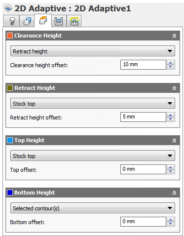
Clearance Height
The Clearance height is the first height the tool rapids to on its way to the start of the tool path.
Clearance Height
- Retract height: incremental offset from the Retract Height.
- Feed height: incremental offset from the Feed Height.
- Top height: incremental offset from the Top Height.
- Bottom height: incremental offset from the Bottom Height.
- Model top: incremental offset from the Model Top.
- Model bottom: incremental offset from the Model Bottom.
- Stock top: incremental offset from the Stock Top.
- Stock bottom: incremental offset from the Stock Bottom.
- Selected contour(s): incremental offset from a Contour selected on the model.
- Selection: incremental offset from a Point (vertex), Edge or Face selected on the model.
- Origin (absolute): absolute offset from the Origin that is defined in either the Setup or in Tool Orientation within the specific operation.
Clearance height offset:
The Clearance height offset is applied and is relative to the Clearance height selection in the above drop-down list.
Retract Height
Retract height sets the height that the tool moves up to before the next cutting pass. Retract height should be set above the Feed height and Top. Retract height is used together with the subsequent offset to establish the height.
Retract Height
- Clearance height: incremental offset from the Clearance Height.
- Feed height: incremental offset from the Feed Height.
- Top height: incremental offset from the Top Height.
- Bottom height: incremental offset from the Bottom Height.
- Model top: incremental offset from the Model Top.
- Model bottom: incremental offset from the Model Bottom.
- Stock top: incremental offset from the Stock Top.
- Stock bottom: incremental offset from the Stock Bottom.
- Selected contour(s): incremental offset from a Contour selected on the model.
- Selection: incremental offset from a Point (vertex), Edge or Face selected on the model.
- Origin (absolute): absolute offset from the Origin that is defined in either the Setup or in Tool Orientation within the specific operation.
Retract height offset:
Retract height offset is applied and is relative to the Retract height selection in the above drop-down list.
Top Height
Top height sets the height that describes the top of the cut. Top height should be set above the Bottom. Top height is used together with the subsequent offset to establish the height.
Top Height
- Clearance height: incremental offset from the Clearance Height.
- Retract height: incremental offset from the Retract Height.
- Feed height: incremental offset from the Feed Height.
- Bottom height: incremental offset from the Bottom Height.
- Model top: incremental offset from the Model Top.
- Model bottom: incremental offset from the Model Bottom.
- Stock top: incremental offset from the Stock Top.
- Stock bottom: incremental offset from the Stock Bottom.
- Selected contour(s): incremental offset from a Contour selected on the model.
- Selection: incremental offset from a Point (vertex), Edge or Face selected on the model.
- Origin (absolute): absolute offset from the Origin that is defined in either the Setup or in Tool Orientation within the specific operation.
Top offset:
Top offset is applied and is relative to the Top height selection in the above drop-down list.
Bottom Height
Bottom height determines the final machining height/depth and the lowest depth that the tool descends into the stock. Bottom height needs to be set below the Top. Bottom height is used together with the subsequent offset to establish the height.
Bottom Height
- Clearance height: incremental offset from the Clearance Height.
- Retract height: incremental offset from the Retract Height.
- Feed height: incremental offset from the Feed Height.
- Top height: incremental offset from the Top Height.
- Model top: incremental offset from the Model Top.
- Model bottom: incremental offset from the Model Bottom.
- Stock top: incremental offset from the Stock Top.
- Stock bottom: incremental offset from the Stock Bottom.
- Selected contour(s): incremental offset from a Contour selected on the model.
- Selection: incremental offset from a Point (vertex), Edge or Face selected on the model.
- Origin (absolute): absolute offset from the Origin that is defined in either the Setup or in Tool Orientation within the specific operation.
Bottom offset:
Bottom offset is applied and is relative to the Bottom height selection in the above drop-down list.
 Passes tab settings
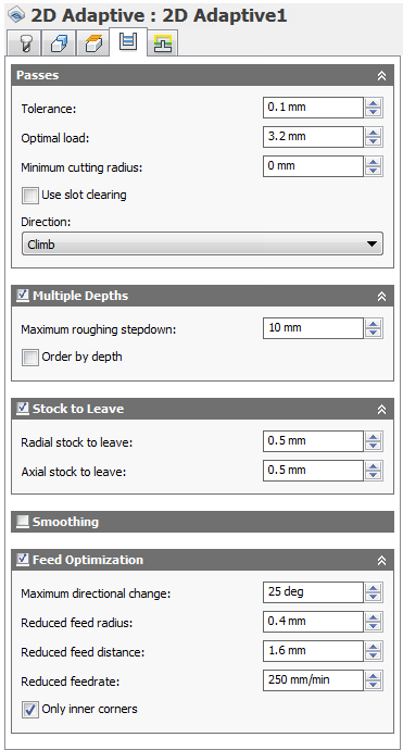
Tolerance:
The tolerance used when linearizing geometry such as splines and ellipses. The tolerance is taken as the maximum chord distance.
Loose Tolerance .100
Tight Tolerance .001
CNC machine contouring motion is controlled using line G1 and arc G2 G3 commands. To accommodate this, CAM approximates spline and surface toolpaths by linearizing them creating many short line segments to approximate the desired shape. How accurately the toolpath matches the desired shape depends largely on the number of lines used. More lines result in a toolpath that more closely approximates the nominal shape of the spline or surface.
Data Starving
It is tempting to always use very tight tolerances, but there are trade-offs including longer toolpath calculation times, large G-code files, and very short line moves. The first two are not much of a problem because Inventor HSM calculates very quickly, and most modern controls have at least 1MB of RAM. However, short line moves, coupled with high feedrates, may result in a phenomenon known as data starving.
Data starving occurs when the control becomes so overwhelmed with data that it cannot keep up. CNC controls can only process a finite number of lines of code (blocks) per second. That can be as few as 40 blocks/second on older machines and 1,000 blocks/second or more on a newer machine like the Haas Automation control. Short line moves and high feedrates can force the processing rate beyond what the control can handle. When that happens, the machine must pause after each move and wait for the next servo command from the control.
Optimal load:
Specifies the amount of engagement the adaptive strategies should maintain.
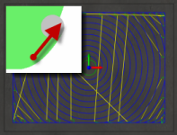
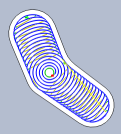
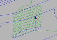
High Speed clearing toolpath
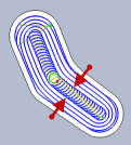
Legacy clearing toolpath
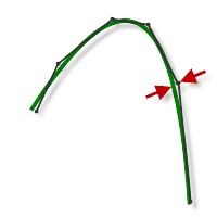
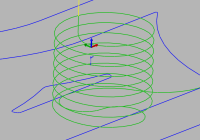
Minimum cutting radius:
With Minimum cutting radius set
With Minimum cutting radius set - Sharp corners in the toolpath are avoided minimizing chatter in finished parts.
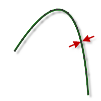
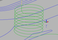
Without Minimum cutting radius set
Without Minimum cutting radius set - The toolpath attempts to remove material anywhere the selected tool can reach. This produces sharp corners in the toolpath that often leads to chatter in the machined part.
Use slot clearing
Enable this setting to start pocket clearing with a slot along its middle before continuing with a spiral motion towards the pocket wall. This feature can be used to reduce linking motion at corners for some pockets.
Use slot clearing enabled
Use slot clearing disabled
Slot clearing width:
The width of the initial clearing slot along the middle of the pocket before continuing with a spiral motion towards the pocket wall.
Slot clearing width
Direction:
The Direction option lets you control if Inventor HSM should try to maintain either Climb or Conventional milling.
Climb
Select Climb to machine all the passes in a single direction. When this method is used, Inventor HSM attempts to use climb milling relative to the selected boundaries.
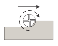
Climb
Conventional
This reverses the direction of the toolpath compared to the Climb setting to generate a conventional milling toolpath.
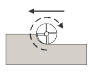
Conventional
Multiple Depths
Specifies that multiple depths should be taken.
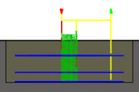
With Multiple Depth cuts
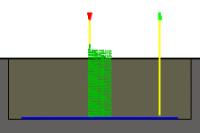
Without Multiple Depth cuts
Maximum roughing stepdown:
Specifies the maximum stepdown between Z-levels for roughing.
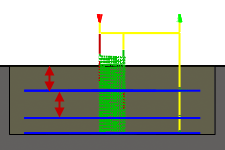
Maximum stepdown - shown without finishing stepdowns
Order by depth
Specifies that the passes should be ordered top down.
Disabled
Enabled
Stock to Leave
Positive
Positive Stock to Leave - The amount of stock left after an operation to be removed by subsequent roughing or finishing operations. For roughing operations, the default is to leave a small amount of material.

None
No Stock to Leave - Remove all excess material up to the selected geometry.
Negative
Negative Stock to Leave - Removes material beyond the part surface or boundary. This technique is often used in Electrode Machining to allow for a spark gap, or to meet tolerance requirements of a part.
Radial (wall) stock to leave
The Radial stock to leave parameter controls the amount of material to leave in the radial (perpendicular to the tool axis) direction, i.e. at the side of the tool.
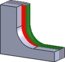
Radial stock to leave
Radial and axial stock to leave
Specifying a positive radial stock to leave results in material being left on the vertical walls and steep areas of the part.
For surfaces that are not exactly vertical, Inventor HSM interpolates between the axial (floor) and radial stock to leave values, so the stock left in the radial direction on these surfaces might be different from the specified value, depending on surface slope and the axial stock to leave value.
Changing the radial stock to leave automatically sets the axial stock to leave to the same amount, unless you manually enter the axial stock to leave.
For finishing operations, the default value is 0 mm / 0 in, i.e. no material is left.
For roughing operations, the default is to leave a small amount of material that can then be removed later by one or more finishing operations.
Negative stock to leave
When using a negative stock to leave, the machining operation removes more material from your stock than your model shape. This can be used to machine electrodes with a spark gap, where the size of the spark gap is equal to the negative stock to leave.
Both the radial and axial stock to leave can be negative numbers. However, the negative radial stock to leave must be less than the tool radius.
When using a ball or radius cutter with a negative radial stock to leave that is greater than the corner radius, the negative axial stock to leave must be less than or equal to the corner radius.
Axial (floor) stock to leave
The Axial stock to leave parameter controls the amount of material to leave in the axial (along the Z axis) direction, i.e. at the end of the tool.
Axial stock to leave
Both radial and axial stock to leave
Specifying a positive axial stock to leave results in material being left on the shallow areas of the part.
For surfaces that are not exactly horizontal, Inventor HSM interpolates between the axial and radial (wall) stock to leave values, so the stock left in the axial direction on these surfaces might be different from the specified value depending on surface slope and the radial stock to leave value.
Changing the radial stock to leave automatically sets the axial stock to leave to the same amount, unless you manually enter the axial stock to leave.
For finishing operations, the default value is 0 mm / 0 in, i.e. no material is left.
For roughing operations, the default is to leave a small amount of material that can then be removed later by one or more finishing operations.
Negative stock to leave
When using a negative stock to leave, the machining operation removes more material from your stock than your model shape. This can be used to machine electrodes with a spark gap, where the size of the spark gap is equal to the negative stock to leave.
Both the radial and axial stock to leave can be negative numbers. However, when using a ball or radius cutter with a negative radial stock to leave that is greater than the corner radius, the negative axial stock to leave must be less than or equal to the corner radius.
Smoothing
Smooths the toolpath by removing excessive points and fitting arcs where possible within the given filtering tolerance.
Smoothing Off

Smoothing On
Smoothing is used to reduce code size without sacrificing accuracy. Smoothing works by replacing collinear lines with one line and tangent arcs to replace multiple lines in curved areas.
The effects of smoothing can be dramatic. G-code file size may be reduced by as much as 50% or more. The machine will run faster and more smoothly and surface finish improves. The amount of code reduction depends on how well the toolpath lends itself to smoothing. Toolpaths that lay primarily in a major plane (XY, XZ, YZ), like parallel paths, filter well. Those that do not, such as 3D Scallop, are reduced less.
Smoothing tolerance:
Specifies the smoothing filter tolerance.
Smoothing works best when the Tolerance (the accuracy with which the original linearized path is generated) is equal to or greater than the Smoothing (line arc fitting) tolerance.
Feed Optimization
Specifies that the feed should be reduced at corners.
Maximum directional change:
Specifies the maximum angular change allowed before the feedrate is reduced.
Reduced feed radius:
Specifies the minimum radius allowed before the feed is reduced.
Reduced feed distance:
Specifies the distance to reduce the feed before a corner.
Reduced feedrate:
Specifies the reduced feedrate to be used at corners.
Only inner corners
Enable to only reduce the feedrate on inner corners.
 Linking tab settings
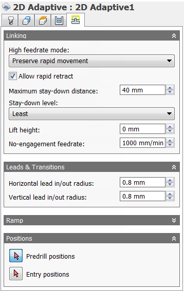
High feedrate mode:
Specifies when rapid movements should be output as true rapids (G0) and when they should be output as high feedrate movements (G1).
- Preserve rapid movement - All rapid movements are preserved.
- Preserve axial and radial rapid movement - Rapid movements that move only horizontally (radial) or vertically (axial) are output as true rapids.
- Preserve axial rapid movement - Only rapid movements moving vertically.
- Preserve radial rapid movement - Only rapid movements moving horizontally.
- Preserve single axis rapid movement - Only rapid movements moving in one axis (X, Y or Z).
- Always use high feed - Outputs rapid movements as (high feed moves) G01 moves instead of rapid movements (G0).
This parameter is usually set to avoid collisions at rapids on machines which perform "dogleg" movements at rapid.
High feedrate:
The feedrate to use for rapids movements output as G1 instead of G0.
Allow rapid retract
When enabled, retracts are done as rapid movements (G0). Disable to force retracts at lead-out feedrate.
Maximum stay-down distance:
Specifies the maximum distance allowed for stay-down moves.
1" Maximum stay-down
2" Maximum stay-down distance
Stay-down level:
Use this setting to control when to stay down rather than doing retracts when moving around obstacles. Generally, you will want the Adaptive strategy to stay-down more if your CNC machine does slow retracts compared to high feed moves. In such cases, increase the level value in the Stay-down level: drop-down menu. Values increase by increments of 10% with the Least setting at 0% and the Most setting at 100%.
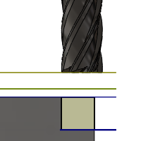
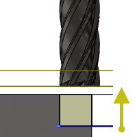
Lift height:
Specifies the lift distance during repositioning moves.
Lift height 0
Lift height .1 in
No-engagement feedrate:
Specifies the feedrate used for movements where the tool is not in engagement on the material, but is also not retracted.
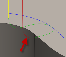
Horizontal lead-in radius:
Specifies the radius for horizontal lead-in moves.
Horizontal lead-in radius
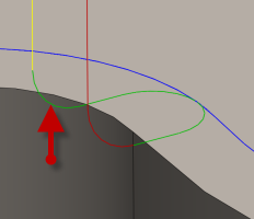
Horizontal lead-out radius:
Specifies the radius for horizontal lead-out moves.
Horizontal lead-out radius
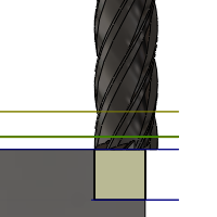
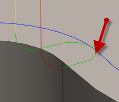
Vertical lead-in radius:
The radius of the vertical arc smoothing the entry move as it goes from the entry move to the toolpath itself.
Vertical lead-in radius
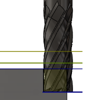
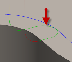
Vertical lead-out radius:
Specifies the radius of the vertical lead-out.
Vertical lead-out radius
Ramp type:
Specifies how the cutter moves down for each depth cut.
Plunge Outside Stock
Predrill
To use the Predrill option, Predrill location(s) must be defined.
Plunge
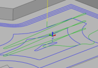
Zig-Zag
Notice the smooth transitions on the Zig-Zag ramp type.
Profile
Smooth Profile
Helix
Ramping angle (deg):
Specifies the maximum ramping angle.
Ramp taper angle (deg):
The desired taper angle of the helical ramps. Use this setting to keep the tool shaft slightly away from the stock and improve chip escape during ramping.
Ramp clearance height:
Height of ramp over the current stock level.
Helical ramp diameter:
Specifies the helical ramp diameter.
Minimum ramp diameter:
Specifies the minimum ramp diameter.
Predrill positions
Select points where holes have been drilled to provide clearance for the cutter to enter the material.
Entry positions
Select geometry near the location where you want the tool to enter.