Begin the contouring operation by running a tool along the outer edges of the part to machine its outer planes.
- On the ribbon, click
CAM tab
 2D Milling panel
2D Contour
2D Milling panel
2D Contour
 .
.
This creates a new operation, and opens the Operation dialog box where you can edit the individual parameters controlling the toolpath, as well as selecting the actual geometry to machine.
Each tab on the Operation dialog box is divided into a number of groups. In this tutorial, the necessary settings are changed in each appropriate group as you go along.
 Tool tab
- On the Tool tab, click the
 button to open the Tool Library dialog box.
 - From the Sample Libraries > Tutorial tool library, select tool #3 - Ø10 mm flat.
- Click
 to close the Tool Library dialog.
 Geometry tab
To machine around the outside outline of the part, select a chain of edges from the model.
- Click the Geometry tab. The Contour selections button should be active.
- Select the bottom front edge on the model. Notice that Inventor HSM automatically creates a chain around the part.
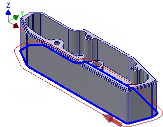
- If the direction arrow does not appear as shown, click the arrow to reverse the toolpath direction.
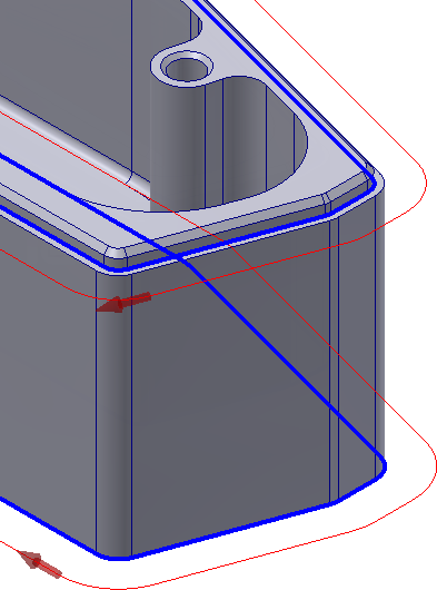
- Zoom in on the top right corner of the part
- Select the edge inside the indent.
You can machine the indent around the top of the part in the same operation.
 Heights tab
By default, the heights for the 2D Contour operation are set so that the bottom of the toolpath is at the level of the selected contours. The remaining heights depend on the stock and model geometry.
If you view the part from the side, it should look like this:
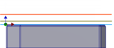
The default height values are fine in this example, and they need not be changed.
Start the Calculation
- Click
 at the bottom of the Operation dialog box, or right-click in the graphics window and select OK from the marking menu, to automatically start calculating the toolpath.
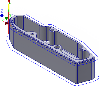
The toolpath is now calculated and a preview appears in the graphics window.
Continue to To Machine the Internal Pocket...