|
Access: |
Ribbon:
CAM tab
 Job panel
Setup
Job panel
Setup

|
Common setup parameters for model orientation and origin, stock selection, stock specifications, and post processing are configured on the Setup operation dialog.
 Setup tab settings
Setup
The machining setup can be described specifying the operation type - milling, turning, or mill/turn. This parameter is made available to the post processor.
Operation Type - Milling
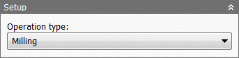
Milling - Use Milling when processing toolpaths for a mill regardless of configuration.
Milling
Operation Type - Turning or Mill/Turn
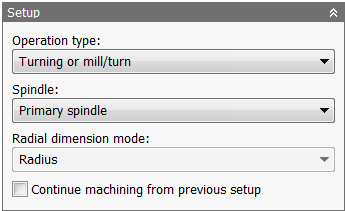
Turning or mill/turn - Use Turning when processing toolpaths for a lathe, including lathes with live tooling and mill/turn configurations.
Turning
Spindle
Specifies the spindle.
- Primary spindle
- Secondary spindle
Radial Dimension Mode
Specifies whether radial dimensions are shown as radius or diameter.
Continue Machining from Previous Setup
Specifies that the machining continues from the previous setup.
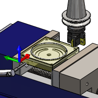
Work Coordinate System (WCS) - Milling
The Work Coordinate System (WCS) specifies the global coordinate system in which the post processed toolpath is output. The WCS defaults to the model orientation.
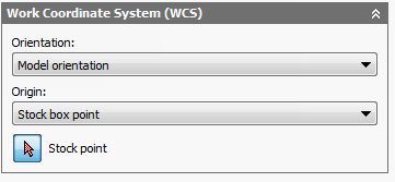
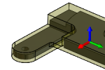
Orientation and Origin options for a milling operation
When editing and simulating, the coordinates are also presented in the WCS by default.
Orientation:
The Orientation: drop-down menu provides the following options to define the setup orientation of the X, Y, and Z WCS axes:
- Model orientation - Uses the orientation of the current part for the WCS orientation.
- Select Z axis/plane & X axis - Select a face or an edge to define the Z axis and another face or edge to define the X axis. Both the Z and X axes can be flipped 180 degrees.
- Select Z axis/plane & Y axis - Select a face or an edge to define the Z axis and another face or edge to define the Y axis. Both the Z and Y axes can be flipped 180 degrees.
- Select X & Y axes - Select a face or an edge to define the X axis and another face or edge to define the Y axis. Both the X and Y axes can be flipped 180 degrees.
- Select coordinate system - Sets the WCS orientation for the setup from an Inventor User Coordinate System (UCS) in the model. This uses both the origin and orientation of the existing coordinate system. Use this option if your model does not contain a suitable point and plane for your operation.
Origin:
The Origin: drop-down menu offers the following options for locating the WCS origin:
- Model origin - Uses the coordinate system (WCS) origin of the current part for the WCS origin.
- Selected point - Select a vertex or an edge for the WCS origin.
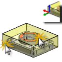
- Stock box point - Select a point on the stock bounding box for the WCS origin.
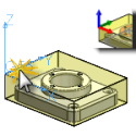
- Model box point - Select a point on the model bounding box for the WCS origin.
The Origin mini-toolbar displays automatically when Setup is invoked and offers an alternative to the dialog box for WCS origin selection.
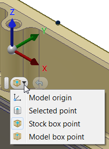
The Origin mini-toolbar drop-down menu. Click the Undo button to the right of the drop-down to reselect the WCS origin.
Orientation & Origin
Coordinate System
Stock Point
Specifies the stock point of the tool view.
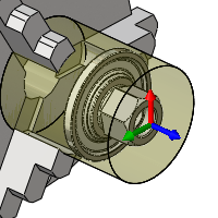
Work Coordinate System (WCS) - Turning or Mill/Turn
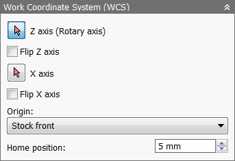
WCS options for a turning or mill/turn operation
- Z Axis (Rotary Axis) - Specifies the axis about which the part rotates.
- Flip Z Axis - Flips the Z axis 180 degrees.
- X Axis - Specifies the X axis of the part.
- Flip X Axis - Flips the X axis 180 degrees.
- Origin - You may choose the Stock front, Stock back, Model front, or Model back as the part origin.
- Home Position - Enter a value to specify the home position along the Z axis.
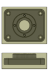
Model
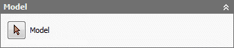
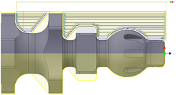
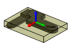
The model specified for the setup is used by default for all 3D surface machining operations. The selected model is also used during the simulation of a toolpath.
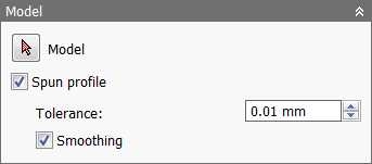
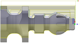
- Spun Profile - Some turned parts require subsequent milling operations. In these instances a turning profile needs to be generated before the milling begins. This feature allow you to generate a 2D sketch profile through the X axis of the mill/turn part which can then be used for turning.
Spun Profile Off
Spun Profile On
- Spun Profile Tolerance - Specifies the tolerance for the spun profile generation.
- Spun Profile Smoothing - Enable to smooth the profile.
Fixture

Select any fixtures that should be included for collision detection when verifying toolpaths during stock simulation.
 Stock tab settings
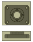
The specified stock and fixture are used when simulating the generated toolpath, and can also be used by some machining strategies.
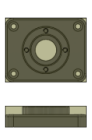
Cubic stock options
Cylindrical stock options

Tube stock options
Mode:
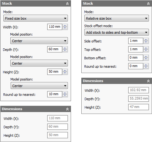
Fixed Size Box and Relative Size Box
Fixed size box - Creates a cubic stock body that is of a specified (fixed) size. This is the default setting.
Relative size box - Creates a cubic stock body that is larger than the model by given offset values, rounded up to the nearest specified increment.
Dimensions - Displays the Width (X), Depth (Y), and Height (Z) dimensions of box setup stock.
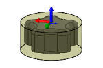
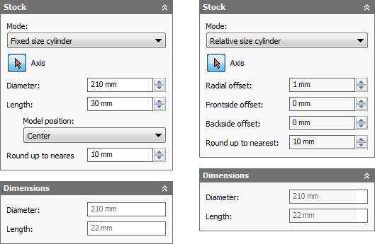
Fixed Size Cylinder and Relative Size Cylinder
Fixed size cylinder - Creates a cylindrical stock body that is of a specified (fixed) size. This is the default setting.
Relative size cylinder - Creates a cylindrical stock body that is larger than the model by given offset values, rounded up to the nearest specified increment.
Dimensions - Displays the diameter and length of cylindrical setup stock.
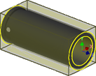
Fixed Size Tube and Relative Size Tube
Fixed size tube - Creates a tube stock body that is of a specified (fixed) size. This is the default setting.
Relative size tube - Creates a tube stock body that is larger than the model by given offset values, rounded up to the nearest specified increment.
Dimensions - Displays the diameter and length of tube setup stock.
From Solid
From Solid - Gives complete control over stock definition by using a solid body in a multi-body part, or from a part file in an assembly.
Dimensions - Displays the Width (X), Depth (Y), and Height (Z) dimensions of the stock.
Fixed Size Box Mode
- Width (X): - Enter a value to specify the stock width.
- Model position: Offset from left side (-X) - Specifies the offset of the stock in the negative X direction.
- Model position: Center - The model is centered along the X axis within the stock.
- Model position: Offset from right side (+X) - Specifies the offset of the stock in the positive X direction.
- Depth (Y): - Enter a value to specify the stock depth.
- Model position: Offset from back side (+Y) - Specifies the offset of the stock in the positive Y direction.
- Model position: Center - The model is centered along the Y axis within the stock.
- Model position: Offset from front side (-Y) - Specifies the offset of the stock in the negative Y direction.
- Height (Z): - Enter a value to specify the stock height.
- Model position: Offset from top (+Z) - Specifies the offset of the stock in the positive Z direction.
- Model position: Center - The model is centered along the Z axis within the stock.
- Model position: Offset from bottom (-Z) - Specifies the offset of the stock in the negative Z direction.
- Round up to nearest: - Specifies the rounding increment for the stock size.
Relative Size Box Mode
Selecting the Relative size box mode provides options to add stock to the top, bottom, and/or sides of the stock.
No additional stock
No additional stock - No offset values are added to the stock size.
Add stock to sides and top-bottom
- Side offset: - Specifies the additional stock on the sides.
- Top offset: - Specifies the additional stock on the top.
- Bottom offset: - Specifies the additional stock on the bottom.
Add stock to all sides
- Stock -X offset: - Specifies the offset of the stock in the negative X direction.
- Stock +X offset:: - Specifies the offset of the stock in the positive X direction.
- Stock -Y offset: - Specifies the offset of the stock in the negative Y direction.
- Stock +Y offset: - Specifies the offset of the stock in the positive Y direction.
- Stock -Z offset: - Specifies the offset of the stock in the negative Z direction.
- Stock +Z offset: - Specifies the offset of the stock in the positive Z direction.
- Round up to nearest: - Specifies the rounding increment for the stock size.
Fixed Size Cylinder Mode
- Axis - Specifies the axis of the cylindrical stock. Permissible selections include arcs, edges, and faces.
- Diameter: - Specifies the diameter of the stock.
- Length: - Specifies the length of the stock.
- Offset from front: - Positions the stock such that it is flush with the front face of the model.
- Center - Centers the model within the cylindrical stock.
- Offset from back - Positions the stock such that it is flush with the back face of the model.
- Round up to nearest: - Specifies the rounding increment for the stock size.
Relative Size Cylinder Mode
Like the Fixed size cylinder mode, the Relative size cylinder mode also lets you specify the axis of the cylindrical stock. In addition, you can specify radial, frontside, and backside offset values to better position your model relative to the stock.
- Axis - Specifies the axis of the cylindrical stock. Permissible selections include arcs, edges, and faces.
- Radial offset: - Specifies the radial offset of the stock.
- Frontside offset: - Specifies the distance to machine beyond the frontside of the model.
- Backside offset: - Specifies the distance to machine beyond the backside of the model.
- Round up to nearest: - Specifies the rounding increment for the stock size.
Fixed Size Tube Mode
- Axis - Specifies the axis of the tube stock. Permissible selections include arcs, edges, and faces.
- Diameter: - Specifies the outer diameter of the tube stock.
- Inner Diameter: - Specifies the inner diameter of the tube stock.
- Length: - Specifies the length of the stock.
- Offset from front: - Positions the stock such that it is flush with the front face of the model.
- Center - Centers the model within the tube stock.
- Offset from back - Positions the stock such that it is flush with the back face of the model.
- Round up to nearest: - Specifies the rounding increment for the stock size.
Relative Size Tube Mode
Like the Fixed size tube mode, the Relative size tube mode also lets you specify the axis of the tube stock. In addition, you can specify radial, frontside, and backside offset values to better position your model relative to the stock.
- Axis - Specifies the axis of the tube stock. Permissible selections include arcs, edges, and faces.
- Radial offset: - Specifies the radial offset of the stock.
- Frontside offset: - Specifies the distance to machine beyond the frontside of the model.
- Backside offset: - Specifies the distance to machine beyond the backside of the model.
- Round up to nearest: - Specifies the rounding increment for the stock size.
 Post Process tab settings
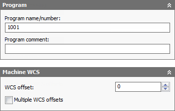
Post processing parameters like the program name or number, program comment, and work offset can be provided on the Post Process tab
The work offset is mapped by the post processor configuration to the corresponding zero table index (e.g. G54-G59) on the CNC control. A value of 1 would normally be setup to be the first available zero index on the CNC control (e.g. G54). The WCS and work offset are generally setup to match one another on a one-to-one basis.
Program name/number
Specifies the program name or number. This parameter is made available to the post processor.
Program comment
Specifies the program comment. This parameter is made available to the post processor.
WCS offset:
Identifies the desired workpiece coordinate system (WCS) for the setup. It is the responsibility of the post processor configuration to map this number to the actual WCS on the machine.
Multiple WCS offsets
Enable this check box to specify that the workpiece is to be duplicated.
WCS offset duplicates:
Specifies the number of workpiece duplicates. This is the total number of instances.
WCS offset increment:
Specifies the work offset increment used for workpiece duplication.
Operation order:
Specifies the ordering of the individual operations.
- Preserve order - Specifies that features are machined in the order in which they were selected.
- Order by operation - Specifies the ordering of the individual operations.
- Order by tool - Specifies the ordering of operations by tool. For example, all operations that use a Ø3/4" flat mill are machined first. Then the next set of operations that use another identical tool, a Ø1/4" flat mill for example, are machined next.
Using Multiple Setup Work Offsets
Inventor HSM supports patterning of entire setups using the Multiple WCS offsets feature, which essentially duplicates entire setups using different work offsets. This feature is generally used when the individual position of each instance is not precisely known.
Once you enable Multiple WCS offsets, you can specify the total number of instances and the work offset increment to be used. You can also choose the order of the duplicated toolpath (by setup, by operation, or by tool).
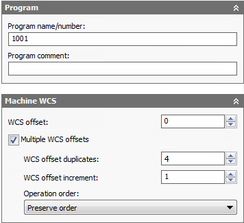
Enabling multiple work offsets
The setting for the WCS offset: field depends on the post processor. In this case we are using a Fanuc post, so specifying 1 will use the first work offset (G54). The next field is the number of duplications, in this case 4, so each of the next offsets is incremented by 1 and will then be G55, G56 and G57.
If the physical setups of each instance are evenly spaced, it is sometimes possible to use a normal pattern feature instead. This allows you to fully simulate the duplicated toolpath. However, this approach requires you to add toolpaths to align the stock for each instance.
Using Backplot to Set Workpiece/Tool Offsets
The Multiple WCS offsets feature only applies to the post processing and setup sheet features. It is not possible to simulate the duplicated toolpath as the relative positions of each instance are not known inside Inventor HSM (e.g. G54 in relation to G55). So to see the multiple work offsets we must look at the posted file in Inventor HSM Edit.
Within the editor, we set the work offsets by first clicking Backplot tab
File panel
Backplot Window
 on the ribbon, and then clicking
Backplot tab
Other panel
Set Workpiece/Tool Offsets
on the ribbon, and then clicking
Backplot tab
Other panel
Set Workpiece/Tool Offsets
 to display the
Workpiece/Tool offsets dialog box.
to display the
Workpiece/Tool offsets dialog box.
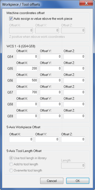
Setting work offsets in Inventor HSM Edit
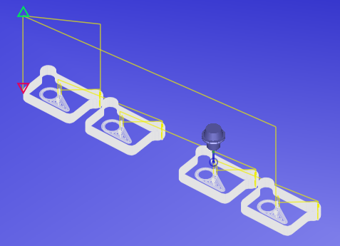
Multiple work offsets in the posted file