Selecting a face (or multiple faces) as the boundary for a 3D finishing operation provides an efficient way of limiting where the tool is machining.
By default, the boundaries confine the tool center points (i.e. the tool center must be inside the boundaries). If the slope of the selected face(s) vary around the edges, the result is either leftover material or machining extending outside the face(s) around the edges.
To avoid the problem, enable the setting Contact point boundary so that the boundaries limit the tool contact points rather than the tool center points.
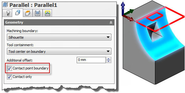
Selecting a face as the machining boundary
The difference is illustrated below on a parallel toolpath using a ball end mill.
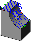
Without boundary
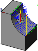
With boundary selected
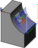
With boundary selected and Contact point boundary enabled
When viewed from the side, you can clearly see the contact point of the tool.
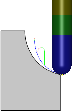
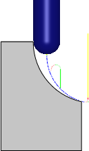
The tool at the extreme contact points