|
Access: |
Ribbon:
CAM tab
 Multi-Axis Milling panel
Swarf
Multi-Axis Milling panel
Swarf

|
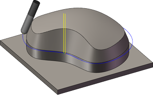
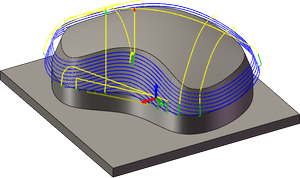
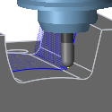
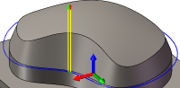
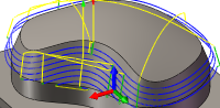
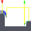
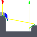
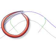
Swarf is a multi-axis strategy for machining with the side of the tool. This strategy supports both machining from contours only and from surfaces. When machining from contours only, you are required to manually synchronize the contours. Swarf supports several different modes that control how to machine down the sides.
Single pass
From bottom
Trim from bottom
From Top
Trim from top
Spiral
Morph
 Tool tab settings
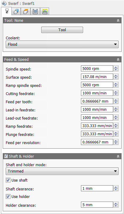
Coolant:
The type of coolant used with the tool.
Spindle speed:
The rotational speed of the spindle.
Surface speed:
The spindle speed expressed as the speed of the tool on the surface.
Ramp spindle speed:
The rotational speed of the spindle when performing ramp movements.
Cutting feedrate:
Feed used in cutting moves.
Feed per tooth:
The cutting feedrate expressed as the feed per tooth.
Lead-in feedrate:
Feed used when leading in to a cutting move.
Lead-out feedrate:
Feed used when leading out from a cutting move.
Ramp feedrate:
Feed used when doing helical ramps into stock.
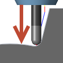
Plunge feedrate:
Feed used when plunging into stock.
Feed per revolution:
The plunge feedrate expressed as the feed per revolution.
Shaft & Holder
When using a tool with a holder, you can choose between one of five different shaft and holder modes, depending on the machining strategy. Collision handling can be done for both the tool shaft and holder, and they can be given separate clearances.
- Disabled - Ignores any shaft/holder collisions.
Disabled
- Pull away - The toolpath pulls away from the workpiece to maintain a safe distance between the shaft and/or holder.
Pull away
- Trimmed - Sections of the toolpath that result in safe distances between the shaft and/or holder being violated are trimmed away.
Trimmed
- Detect tool length - The tool is automatically extended further out of the holder to maintain the specified safe distance between the shaft and/or holder and the workpiece. A message indicating how the far the tool is extended out of the holder is logged.
Detect tool length
- Fail on collision - The toolpath calculation is aborted and an error message logged when the safe distance is violated.
Use shaft
Specifies that the shaft of the selected tool will be used in the toolpath calculation to avoid collisions.
Shaft clearance:
The tool shaft always stays this distance from the part.
Use holder
Specifies that the holder of the selected tool will be used in the toolpath calculation to avoid collisions.
Holder clearance:
The tool holder always stays this distance from the part.
 Geometry tab settings
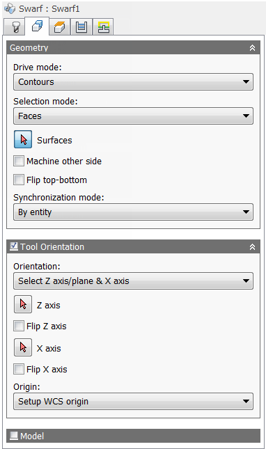
Drive mode:
Machining from contours only or from surfaces are both supported. Choose Contours or Surfaces from the drop-down menu.
Selection mode:
- Faces -
- Contour pairs -
- Manual -
Surfaces
Selection button to choose the surfaces to be machined.
Machine other side
Flip top-bottom
Synchronization mode
Selecting Contours from the Drive mode: drop-down menu provides the following synchronization options:
- Manual -
- By entity -
- Shortest distance -
- Constant slope -
- Automatic -
Tool Orientation
Specifies how the tool orientation is to be determined using a combination of triad orientation and origin options.
The Orientation drop-down menu provides the following options to set the orientation of the X, Y, and Z triad axes:
- Setup WCS orientation - Uses the workpiece coordinate system (WCS) of the current setup for the tool orientation.
- Model orientation - Uses the coordinate system (WCS) of the current part for the tool orientation.
- Select Z axis/plane & X axis - Select a face or an edge to define the Z axis and another face or edge to define the X axis. Both the Z and X axes can be flipped 180 degrees.
- Select Z axis/plane & Y axis - Select a face or an edge to define the Z axis and another face or edge to define the Y axis. Both the Z and Y axes can be flipped 180 degrees.
- Select X & Y axes - Select a face or an edge to define the X axis and another face or edge to define the Y axis. Both the X and Y axes can be flipped 180 degrees.
- Select coordinate system - Sets a specific tool orientation for this operation from an Inventor User Coordinate System (UCS) in the model. This uses both the origin and orientation of the existing coordinate system. Use this if your model does not contain a suitable point & plane for your operation.
The Origin drop-down menu offers the following options for locating the triad origin:
- Setup WCS origin - Uses the workpiece coordinate system (WCS) origin of the current setup for the tool origin.
- Model origin - Uses the coordinate system (WCS) origin of the current part for the tool origin.
- Selected point - Select a vertex or an edge for the triad origin.
- Stock box point - Select a point on the stock bounding box for the triad origin.
- Model box point - Select a point on the model bounding box for the triad origin.
Model
Enable to override the model geometry (surfaces/bodies) defined in the setup.
Include setup model
Enabled by default, the model selected in the setup is included in addition to the model surfaces selected in the operation. If you disable this check box, then the toolpath is generated only on the surfaces selected in the operation.
 Heights tab settings
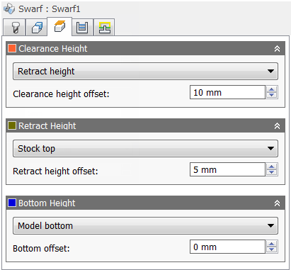
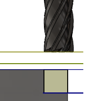
Clearance Height
The Clearance height is the first height the tool rapids to on its way to the start of the tool path.
Clearance Height
- Retract height: incremental offset from the Retract Height.
- Bottom height: incremental offset from the Bottom Height.
- Model top: incremental offset from the Model Top.
- Model bottom: incremental offset from the Model Bottom.
- Stock top: incremental offset from the Stock Top.
- Stock bottom: incremental offset from the Stock Bottom.
- Selection: incremental offset from a Point (vertex), Edge or Face selected on the model.
- Origin (absolute): absolute offset from the Origin that is defined in either the Setup or in Tool Orientation within the specific operation.
Clearance height offset:
The Clearance height offset is applied and is relative to the Clearance height selection in the above drop-down list.
Retract Height
Retract height sets the height that the tool moves up to before the next cutting pass. Retract height should be set above the Feed height and Top. Retract height is used together with the subsequent offset to establish the height.
Retract Height
- Clearance height: incremental offset from the Clearance Height.
- Bottom height: incremental offset from the Bottom Height.
- Model top: incremental offset from the Model Top.
- Model bottom: incremental offset from the Model Bottom.
- Stock top: incremental offset from the Stock Top.
- Stock bottom: incremental offset from the Stock Bottom.
- Selection: incremental offset from a Point (vertex), Edge or Face selected on the model.
- Origin (absolute): absolute offset from the Origin that is defined in either the Setup or in Tool Orientation within the specific operation.
Retract height offset:
Retract height offset is applied and is relative to the Retract height selection in the above drop-down list.
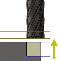
Bottom Height
Bottom height determines the final machining height/depth and the lowest depth that the tool descends into the stock. Bottom height needs to be set below the Top. Bottom height is used together with the subsequent offset to establish the height.
Bottom Height
- Clearance height: incremental offset from the Clearance Height.
- Retract height: incremental offset from the Retract Height.
- Model top: incremental offset from the Model Top.
- Model bottom: incremental offset from the Model Bottom.
- Stock top: incremental offset from the Stock Top.
- Stock bottom: incremental offset from the Stock Bottom.
- Selection: incremental offset from a Point (vertex), Edge or Face selected on the model.
- Origin (absolute): absolute offset from the Origin that is defined in either the Setup or in Tool Orientation within the specific operation.
Bottom offset:
Bottom offset is applied and is relative to the Bottom height selection in the above drop-down list.
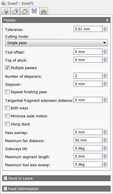
 Passes tab settings
Tolerance
The machining tolerance is the sum of the tolerances used for toolpath generation and geometry triangulation. Any additional filtering tolerances must be added to this tolerance to get the total tolerance.
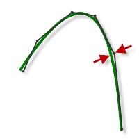
Loose Tolerance .100
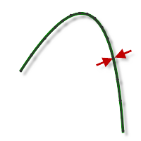
Tight Tolerance .001
CNC machine contouring motion is controlled using line G1 and arc G2 G3 commands. To accommodate this, CAM approximates spline and surface toolpaths by linearizing them; creating many short line segments to approximate the desired shape. How accurately the toolpath matches the desired shape depends largely on the number of lines used. More lines result in a toolpath that more closely approximates the nominal shape of the spline or surface.
Data Starving
It is tempting to always use very tight tolerances, but there are trade-offs including longer toolpath calculation times, large G-code files, and very short line moves. The first two are not much of a problem because Inventor HSM calculates very quickly and most modern controls have at least 1MB of RAM. However, short line moves, coupled with high feedrates, may result in a phenomenon known as data starving.
Data starving occurs when the control becomes so overwhelmed with data that it cannot keep up. CNC controls can only process a finite number of lines of code (blocks) per second. That can be as few as 40 blocks/second on older machines and 1,000 blocks/second or more on a newer machine like the Haas Automation control. Short line moves and high feedrates can force the processing rate beyond what the control can handle. When that happens, the machine must pause after each move and wait for the next servo command from the control.
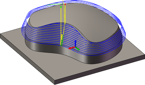
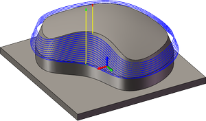
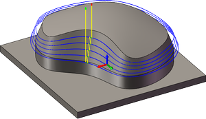
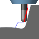
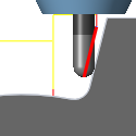
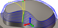
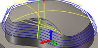
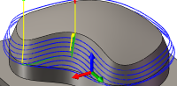
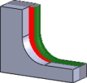
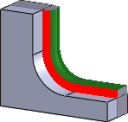
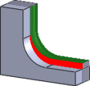
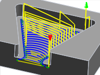
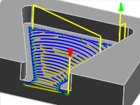
Cutting mode:
The cutting mode specifies how to machine down the sides.
Single pass
From bottom
Trim from bottom
From top
Trim from top
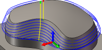
Spiral
Morph
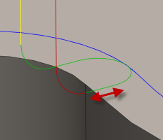
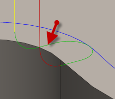
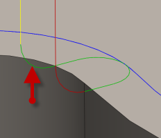
Tool offset:
Specifies an extra offset along the tool axis relative to the bottom guide curve.
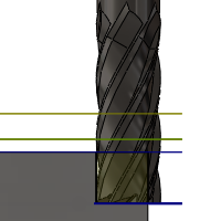
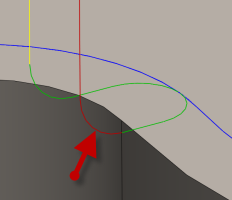
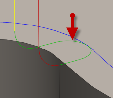
Top of stock:
Specifies the overall thickness of the stock.
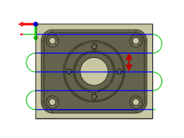
Multiple passes
Enable to enter a stepover value.
Number of stepovers:
The number of roughing steps.
Stepover:
Specifies the horizontal stepover between passes. By default, this value is 95% of the cutter diameter less the tool corner radius.
Horizontal stepover
Repeat finishing pass
Enable to perform the final finishing pass twice to remove stock left due to tool deflection.
Tangential fragment extension distance:
Specifies the tangential extension of the passes.
Both ways
Specifies that the operation uses both Climb and Conventional milling to machine open profiles.
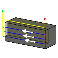
Unselected
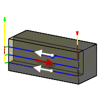
Selected
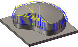
Minimize axial motion
Along stock
Pass overlap:
Specifies the distance to extend machining for a closed pass.
Maximum fan distance:
Specifies the maximum distance over which to fan the tool axis.
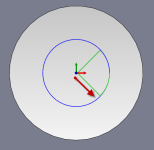
Sideways tilt:
Specifies the number of degrees the tool should be tilted sideways.
Maximum segment length:
Specifies the maximum length of a single segment for the generated toolpath.
Maximum tool axis sweep:
Specifies the maximum angle change in a single tool axis sweep for the generated toolpath.
Stock to Leave
Positive
Positive Stock to Leave - The amount of stock left after an operation to be removed by subsequent roughing or finishing operations. For roughing operations, the default is to leave a small amount of material.

None
No Stock to Leave - Remove all excess material up to the selected geometry.
Negative
Negative Stock to Leave - Removes material beyond the part surface or boundary. This technique is often used in Electrode Machining to allow for a spark gap, or to meet tolerance requirements of a part.
Radial (wall) stock to leave
The Radial stock to leave parameter controls the amount of material to leave in the radial (perpendicular to the tool axis) direction, i.e. at the side of the tool.
Radial stock to leave
Radial and axial stock to leave
Specifying a positive radial stock to leave results in material being left on the vertical walls and steep areas of the part.
For surfaces that are not exactly vertical, Inventor HSM interpolates between the axial (floor) and radial stock to leave values, so the stock left in the radial direction on these surfaces might be different from the specified value, depending on surface slope and the axial stock to leave value.
Changing the radial stock to leave automatically sets the axial stock to leave to the same amount, unless you manually enter the axial stock to leave.
For finishing operations, the default value is 0 mm / 0 in, i.e. no material is left.
For roughing operations, the default is to leave a small amount of material that can then be removed later by one or more finishing operations.
Negative stock to leave
When using a negative stock to leave, the machining operation removes more material from your stock than your model shape. This can be used to machine electrodes with a spark gap, where the size of the spark gap is equal to the negative stock to leave.
Both the radial and axial stock to leave can be negative numbers. However, the negative radial stock to leave must be less than the tool radius.
When using a ball or radius cutter with a negative radial stock to leave that is greater than the corner radius, the negative axial stock to leave must be less than or equal to the corner radius.
Axial (floor) stock to leave
The Axial stock to leave parameter controls the amount of material to leave in the axial (along the Z-axis) direction, i.e. at the end of the tool.
Axial stock to leave
Both radial and axial stock to leave
Specifying a positive axial stock to leave results in material being left on the shallow areas of the part.
For surfaces that are not exactly horizontal, Inventor HSM interpolates between the axial and radial (wall) stock to leave values, so the stock left in the axial direction on these surfaces might be different from the specified value depending on surface slope and the radial stock to leave value.
Changing the radial stock to leave automatically sets the axial stock to leave to the same amount, unless you manually enter the axial stock to leave.
For finishing operations, the default value is 0 mm / 0 in, i.e. no material is left.
For roughing operations, the default is to leave a small amount of material that can then be removed later by one or more finishing operations.
Negative stock to leave
When using a negative stock to leave the machining operation removes more material from your stock than your model shape. This can be used to machine electrodes with a spark gap, where the size of the spark gap is equal to the negative stock to leave.
Both the radial and axial stock to leave can be negative numbers. However, when using a ball or radius cutter with a negative radial stock to leave that is greater than the corner radius, the negative axial stock to leave must be less than or equal to the corner radius.
Feed Optimization
Specifies that the feed should be reduced at corners.
Maximum directional change:
Specifies the maximum angular change allowed before the feedrate is reduced.
Reduced feed radius:
Specifies the minimum radius allowed before the feed is reduced.
Reduced feed distance:
Specifies the distance to reduce the feed before a corner.
Reduced feedrate:
Specifies the reduced feedrate to be used at corners.
Only inner corners
Enable to only reduce the feedrate on inner corners.
 Linking tab settings
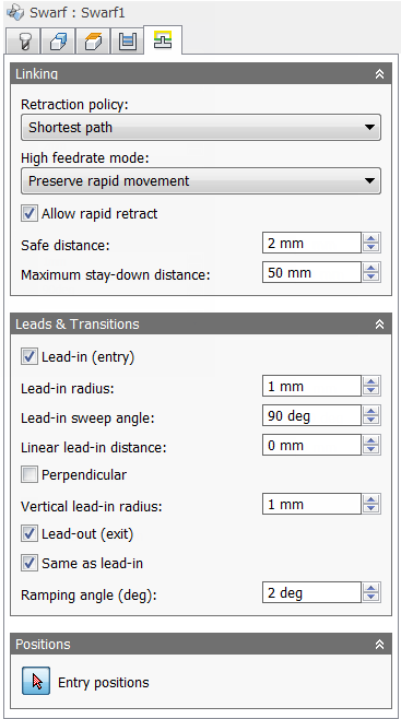
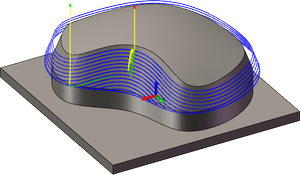
Retraction policy:
Controls how the tool moves between cutting passes. The following images are shown using the Flow strategy.
- Full retraction - completely retracts the tool to the Retract Height at the end of the pass before moving above the start of the next pass.
- Minimum retraction - moves straight up to the lowest height where the tool clears the workpiece, plus any specified safe distance.

- Shortest path - moves the tool the shortest possible distance in a straight line between paths.
Caution: The Shortest path option should not be used on machines that do not support linearized rapid movements where G0 moves are straight-line (versus G0 moves that drive all axes at maximum speed, sometimes referred to as "dogleg" moves). Failure to obey this rule will result in machine motion that cannot be properly simulated by the software and may result in tool crashes.
For CNC machines that do not support linearized rapid moves, the post processor can be modified to convert all G0 moves to high-feed G1 moves. Contact technical support for more information or instructions how to modify post processors as described.
High feedrate mode:
Specifies when rapid movements should be output as true rapids (G0) and when they should be output as high feedrate movements (G1).
- Preserve rapid movement - All rapid movements are preserved.
- Preserve axial and radial rapid movement - Rapid movements moving only horizontally (radial) or vertically (axial) are output as true rapids.
- Preserve axial rapid movement - Only rapid movements moving vertically.
- Preserve radial rapid movement - Only rapid movements moving horizontally.
- Preserve single axis rapid movement - Only rapid movements moving in one axis (X, Y or Z).
- Always use high feed - Outputs rapid movements as (high feed moves) G01 moves instead of rapid movements (G0).
This parameter is usually set to avoid collisions at rapids on machines which perform "dog-leg" movements at rapid.
High feedrate:
The feedrate to use for rapids movements output as G1 instead of G0.
Allow rapid retract
When enabled, retracts are done as rapid movements (G0). Disable to force retracts at lead-out feedrate.
Safe distance:
Minimum distance between the tool and the part surfaces during retract moves. The distance is measured after stock to leave has been applied, so if a negative stock to leave is used, special care should be taken to ensure that safe distance is large enough to prevent any collisions.
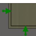
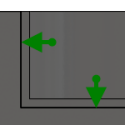
Maximum stay-down distance:
Specifies the maximum distance allowed for stay-down moves.
1" Maximum stay-down distance
2" Maximum stay-down distance
Lead-in (entry)
Enable to generate a lead-in.
Lead-in
Lead-in radius:
Specifies the radius for lead-in moves.
Lead-in radius
Lead-in sweep angle:
Specifies the sweep of the lead-in arc.
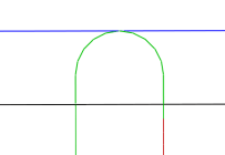
Sweep angle @ 90 degrees
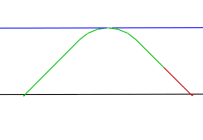
Sweep angle @ 45 degrees
Linear lead-in distance:
Specifies the length of the linear lead-in move for which to activate radius compensation in the controller.
Linear lead-in distance
Perpendicular
Replaces tangential extensions of lead-in/lead-out arcs with a move perpendicular to the arc.
Shown with Perpendicular entry/exit
Example: A bore that has lead arcs that are as large as possible (the larger the arc the less chance of dwell mark), and where a tangent linear lead is not possible because it would extend into the side of the bore.
Vertical lead-in radius:
The radius of the vertical arc smoothing the entry move as it goes from the entry move to the toolpath itself.
Vertical lead-in radius
Lead-out (exit)
Enable to generate a lead-out.
Lead-out
Same as lead-in
Specifies that the lead-out definition should be identical to the lead-in definition.
Linear lead-out distance:
Specifies the length of the linear lead-out move for which to deactivate radius compensation in the controller.
Linear lead-out distance
Lead-out radius:
Specifies the radius for lead-out moves.
Lead-out radius
Vertical lead-out radius:
Specifies the radius of the vertical lead-out.
Vertical lead-out radius
Lead-out sweep angle:
Specifies the sweep of the lead-out arc.
Ramping angle (deg):
Specifies the maximum ramping angle.
Entry positions
Selection button to choose entry positions.