An assembly file has a master Positional representation that represents the default state of the assembly. When you create a new Positional representation, the master is copied.
Create a positional representation of an assembly
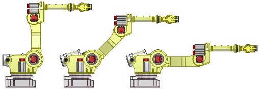
Use positional representations to show an assembly in different positions. For example, fully open or fully closed.
- In the browser, click to expand the Representations folder.
- Right-click Position, and then select New. The new Positional representation is activated and nested below the master, using the default name Position1.
- Additional representation names are incremented unless you change the name.
- If appropriate, click the Positional representation in the browser, and then enter a new name.
- Establish overrides to relationships and components.
- Click Save to save changes. The Positional representation is saved in the assembly file.
Create a positional representation of a mold base
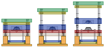
The following positional representations are created when you insert a mold base:
- Product open
- Ejection
- Close
- Free Drag
Use the positional representations to evaluate the mold base in various positions, such as Product Open, and Ejection for interference or other violations.
Note: The Representations folder is not available in the Mold Design browser view. Set the browser filter to either the Model or Representations browser to view the Representations folder. Expand the Position node to view the mold base positional representations.
- Open a top-level assembly that includes a current mold base.
- In the Model browser, click the Representations folder to expand.
- Right click the Position entry to create a new positional representation, or right-click an existing one (not the master positional representation), and then select Activate.
The assembly reconfigures. Further edits to the model are suspended until the mold base Master representation is activated.
- Examine the effect of the changes on the mold base and determine the adjustments required to accommodate the different positions.
- Check for interference.
- Check for clearance violations.
- Optionally, activate the Free Drag representation and then enter the dynamic simulation environment for further mold analysis. All kinematic constraints are suppressed in the Free Drag representation.
- Activate the Master positional representation and return to the top-level assembly to perform further edits and updates to the mold.
Note: Use Inventor Studio to animate a sequence of positional representations. Use positional representations as an Overlay view in a drawing to show the mold in different positions.