Valve gate controllers are required to control the opening and closing of valve gates associated with hot runner systems. The more control you have over the valve gates, the better the appearance of the part, but the more expensive the system.
Valve gates can be opened all at the same time, or sequentially. Some controllers are ideal for regular molding machines without sequential fill capability. For long parts, with multiple gates, opening the gates sequentially, after the polymer melt has passed by them, eliminates blemishes that can occur with uncontrolled plastic flow.
In addition to sequential or co-temporal valve gate opening, some valve gates open instantly, while some valve gates can be programmed to open in a velocity controlled manner to slow the initial flow of melt into the cavity and reduce pressure peaks and flow marks associated with instant opening. The combination of controlled valve gate opening with sequential valve gating provides the highest quality molding surfaces of all.
 Midplane
  Dual Domain
Valve pin geometry for the simulation of velocity controlled valve pin movement
- The valve pin tip, that is, the section that comes into contact with the gate channel when fully closed, is assumed to follow the gate channel geometry for velocity controlled pin movement.
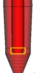
Valve pin tip
- The small end of the valve pin is assumed to be flush with the end of the gate.
- The nominal pin diameter must be specified for the straight section of the valve pin.
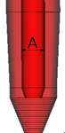
Nominal pin diameter (A)
- Any pin tip geometry, that cannot be accounted for by the nominal pin diameter and the gate channel geometry, is ignored.
Valve gate modeling guidelines
- Valve gates can only be used in conjunction with hot runners.
- Valve gates must be modeled with the valve pin in the open position, regardless of the initial state (open or closed) of the valve gate, to ensure that the dimensions of the valve gate beams are correct, and to ensure that there are no annular beam elements created with zero cross-section area, which could occur if modeled in the closed position.
- A valve gate must be assigned to a single hot gate element in each hot drop. For Gas-assisted Fill+Pack analysis, a valve gate can also be assigned to an overflow well (modeled using Midplane or beam elements for Midplane models, and tetrahedral elements for 3D models).
- A valve gate must not be assigned to the same element as an injection location. You should either model the feed system ahead of the valve gate, or ensure that the gate is meshed with more than one element along its length and then assign the valve gate to the gate element attached to the part.
- A valve gate is assigned to a hot gate or overflow well element by selecting a valve gate controller on the Valve Control tab of the properties dialog for the element. The properties that you assign to the valve gate controller specify the initial state and on/off timings of the valve gate.
- Each valve gate controller should have a unique name to identify it. The same valve gate controller can be assigned to more than one hot gate or overflow well element. To ensure you have set the correct controller at each gate, use a different property name for each valve gate controller and gate element.
- Valve gate controllers operate independently. One valve gate does not have the ability to close when the flow front reaches another valve gate.