Geometry remapping for hardware rendering

The following information focuses on the remapping of geometry data that can occur:
-
From the point of creation of polygonal meshes, either internally or via the MFnMesh API interface,
-
To the point where geometry is provided for hardware rendering.
The main goal is to describe how the vertex data provided at render time can be mapped back to the original geometry. In particular, we consider the case where the requirement is to remap data back to a series of original quadrilateral (quad) faces. Such is the case for Ptex texture mapping.
To start, basic triangulation logic and uniform subdivision logic used for the Smooth Mesh Preview display option is described. This information can aid in understanding the algorithm performed by custom remapping which matches what is performed internally by Maya. This information pertains to the logic in Maya 2016 and is applicable for both VP1 (Legacy Default Viewport) and VP2 (Viewport 2.0).
Secondly, access to remapping data at shading time is examined. The main advantage of using remapped data is that the plug-in does not need to keep up with the complexity of internal logic changes within Maya. The provided data has already undergone all internal data manipulation in the same manner as other per-vertex attributes (such as positions and normals).
The internal remapping logic is current as of Maya 2016 and is subject to change over time. Reverse-engineering this logic is not recommended. In addition, the index remapping logic used for triangulation and sculpting performance, as well as adaptive subdivision, add additional complexity and non-determinism for VP2.
Access to equivalent remapping data for both VP1 and VP2 hardware shader interfaces are also examined.
Remapping logic
Triangulation
Triangulation occurs in order to produce geometric indexing, which can be used when hardware rendering. The choice of which local vertex indices are used for splitting is determined by the triangulation logic. Knowledge of which split is used can aid in determining the mapping of a pair of triangles back to the original quad.
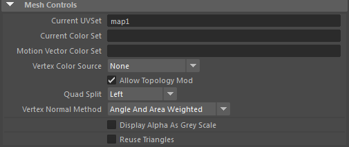
By default, the logic used for polygonal shapes attempt to provide the best shaped triangles. However, for remapping, the overriding goal is to obtain predictability as to how the splitting occurs. As such, the quadSplit attribute on mesh shapes can be set to improve predictability.
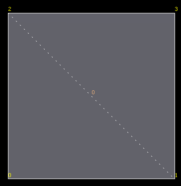
The quadSplit option determines how quads are split into two triangles. If Left is selected, then the new edge will be between the 2nd and 4th vertex, while Right splits between the 1st and 4th vertex. Best Shape attempts to pick the best split based on the shape of the quad, but this may change as the shape deforms across an animation.
Thus, selecting either a Left or Right split will provide greater predictability.
A Left split is shown in the images below. The dotted line shows where the split occurred.
If Best Shape is still desired, the reference logic for a quad is given below. The general algorithm handles general N-sided polygons, which may have holes, but is not included here.
v0 = quad vertex 0
v1 = quad vertex 1
v2 = quad vertex 2
v3 = quad vertex 3

dist02 = distance between v0 and v2
dist13 = distance between v1 and v3

// Use small tolerance so exact squares triangulate consistently
// one way rather than randomly due to rounding errors
fudgeFactor = 0.999f
canSplit = false
split02 = false

if( dist02 < fudgeFactor*dist13 )
{
    n1 = normal of triangle 1, 2, 0
    n2 = normal of triangle 2, 3, 0

    if( angle between n1 and n2 is less than 90 degrees )
    {
        if( area of triangle1 < 7 * area of triangle2 &&
                    area of triangle2 < 7 * area of triangle1 )
        {
            canSplit = true
            split02 = true
        }
    }
}
else
{
    n1 = normal of triangle 0, 1, 3
    n2 = normal of triangle 3, 1, 2

    if( angle between n1 and n2 is less than 90 degrees )
    {
        if( area of triangle1 < 7 * area of triangle2 &&
                area of triangle2 < 7 * area of triangle1 )
        {
            canSplit = true
            split02 = false
        }
    }
}

if( canSplit )
{
    if( split02 )
    {
        set triangle 1 = 1,2,0
        set triangle 2 = 0,2,3
    }
    else
    {
        set triangle 1 = 0,1,3
        set triangle 2 = 3,1,2
    }
}
else
{
   // Fall back to general triangulation algorithm
}
MFnMesh considerations
The triangulation option on MFnMesh differs from those used internally and will always use a best shape option.
Remapping of indexing does not occur if the triangulation method on MFnMesh is not called, and the interfaces that provide data for storage on an MFnMesh do not reshuffle any data passed in. If the triangulation method is not called, then the internal triangulation logic will take into account the quadSplit option.
Subdivision
The Smooth Mesh Preview option on polygonal shapes is another occasion where the original geometric data may be remapped. As the geometry provided at rendering will have a smoothing algorithm applied to produce a new set of geometry, additional logic is required to not only handle indexing on existing vertices, but also new vertices that have been introduced along with the corresponding new indexing.
The following sections discuss the mapping logic (rules) for uniform subdivision when using either OpenSubiv (OSD) or legacy Catmull-Clark logic. In particular, the winding order of vertices and faces and the local parametric (UV) location of new vertices is covered. The local parameterization can be remapped to texture coordinates as required for texture map lookups.
We refer to the original geometry as the base geometry. For example, an original face is a base face.
Maya uniform OpenSubdiv subdivision
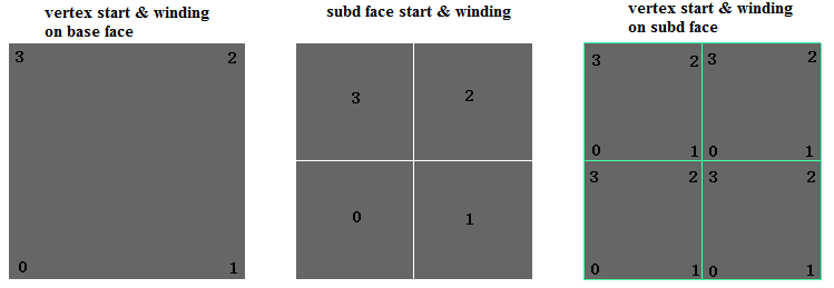
The figure above shows a base face (left image) and the start and winding order of the subdivided faces and vertices when 1 level of subdivision is applied (center and right images).
Levels closer to the base level are considered as being higher. The subdivided face ordering is thus shown to be consistent with higher levels. The start face is in the bottom-left corner which aligns to the start vertex on the base face. Similarly, the vertices on the subdivided faces also start from the bottom-left corner. The winding order is always counter-clockwise (CCW).
Assuming the origin of the local UV is located at vertex 0 of the base face, it is possible to deduce the local UV's of the vertices on the subdivided faces.
The following is the some sample code to determine the local parametric value.
// Get the UV of the bottom-left corner of the subdivided face.
//
// - subdFaceIndex, the index of subdivided face within a base face.
// - subdLevel, the Catmull-Clark subdivision level
//
// such that:
//
// - subdLevel >= 1
// - 0 <= subdFaceIndex <= 4^subdLevel
// - the UV value is encoded as an integer within [0, 2^subdLevel].
//
getSubFaceUV(subdFaceIndex, subdLevel)
{
    uv = (0,0);

    count = pow(4, subdLevel - 1);
    ofs = pow(2, subdLevel - 1);

    // Iteratively find the index of a parent face in each subdivision level,
    // and offset the UV accordingly.
    faceIndex = subdFaceIndex;
    while (count > 0) {
        start = faceIndex / count;
        switch (start) {
            case 0:                  break;
            case 1: uv += (ofs,0);   break;
            case 2: uv += (ofs,ofs); break;
            case 3: uv += (0,ofs);   break;
        }

        faceIndex %= count;
        ofs >>= 1;
        count >>= 2;
    }
    return uv;
}

// Get the UV of the vertex on the subdivided face.
//
// - subdFaceStartUV: the UV of the bottom-left corner of the subd face.
// - subdVertexIndex: vertex index on the subdivided face, 0~3.
//
getSubVertexUV(subdFaceStartUV, subdVertexIndex) {
    uv = (0,0);
    switch (subdVertexIndex) {
        case 0:              break;
        case 1: uv += (1,0); break;
        case 2: uv += (1,1); break;
        case 3: uv += (0,1); break;
    }
    return subdFaceStartUV + uv;
}

subdFaceStartUV = getSubFaceUV(subdFaceIndex, subdLevel);
subdVertexUV = getSubVertexUV (subdFaceStartUV, subdVertexIndex);
subdVertexUV /= pow(2, subdLevel);
Maya legacy Catmull-Clark subdivision
The logic for Maya legacy subdivision is a little more complex.
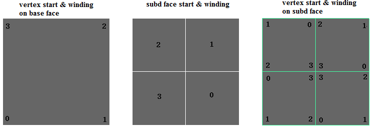
The figure above shows a base face (left) and the start and winding order of the subdivided faces and vertices when 1 level of subdivision is applied (center and right images). The start of the subdivided face aligns to the second (index = 1) vertex on the base face, while the starting vertex continues to shift accordingly, based on the subdivided face number.
The following is the sample code. The sections of the code that differ from that of the OpenSubdiv algorithm is highlighted in bold.
// Get the UV of the bottom-left corner of the subdivided face.
//
// - subdFaceIndex, the index of subdivided face within a base face
// - subdLevel, the Catmull-Clark subdivision level
//
// such that:
//
// - subdLevel >= 1.
// - 0 <= subdFaceIndex <= 4^subdLevel,
// - the uv is encoded as integer within [0, 2^subdLevel].
//
getSubFaceUV(subdFaceIndex, subdLevel) {
    uv = (0,0);
    start = 1;

    count = pow(4, subdLevel - 1);
    ofs = pow(2, subdLevel - 1);

    // Iteratively find the index of parent face in each subdivision level,
    // and offset the UV's accordingly.
    faceIndex = subdFaceIndex;
    while (count > 0) {
        // Unlike OSD subdivided topology, the start position of the child face
        // is related to that of the parent face.
        start = (start + faceIndex / count) % 4;
        switch (start) {
            case 0:                  break;
            case 1: uv += (ofs,0);   break;
            case 2: uv += (ofs,ofs); break;
            case 3: uv += (0,ofs);   break;
        }

        faceIndex %= count;
        ofs >>= 1;
        count >>= 2;
    }
    // The start position of the face is also returned.
    return (uv, start);
}

// Get the uv of the vertex on the subdivided face.
//
// - subdFaceStartUV, the UV of the bottom-left corner of the subdivided face.
// - subdVertexIndex, vertex index on the subdivided face, 0~3.
//
getSubVertexUV(subFaceStartIndex, subFaceStartUV, subdVertexIndex) {
    uv = (0,0);
    // Unlike OSD subdivided topology, the start of the vertex relies on
    // the start position of the face.
    start = (subdFaceIndex - 1 + 4) % 4;
    switch ((start + subdVertexIndex) % 4) {
        case 0:              break;
        case 1: uv += (1,0); break;
        case 2: uv += (1,1); break;
        case 3: uv += (0,1); break;
    }
    return subFaceStartUV + uv;
}

(subdFaceStartUV, start) = getSubFaceUV(subdFaceIndex, subdLevel);
subdVertexUV = getSubVertexUV(start, subdFaceStartUV, subdVertexIndex);
subdVertexUV /= pow(2, subdLevel);
Data remapping interfaces
For both Viewport 1 and Viewport 2.0, it is possible to retrieve remapped data by specifying the requirement for the following data buffers via the appropriate hardware shader interface. The following remapping data is currently available:
-
Vertex ids
-
Face ids
-
Per face local parameterization
The data can be used directly instead of computing the remapping at draw time using the logic previously described. In addition, the data is cached and is only updated as required when topological operations affect the polygonal shape.
When an object’s geometry has not been smoothed for display:
- The original face ids are returned in ascending order.
-
The original vertex ids are returned per face.
-
The local parameterization degenerates to a unit square per face.
When smoothing for display is enabled:
-
The base face ids are returned. The ordering is per subdivided faces in ascending order.
-
The subdivided vertex ids are returned. The ordering is per subdivided faces in ascending order. As vertices may be generated for display purposes, there will be vertex ids that do not correspond to any vertex on the base mesh. If desired, these vertices can be matched with the vertex ids on the smooth mesh geometry extracted via the MFnMesh interface.
-
The local parameterization maps each vertex to a unit square on the base face. The ordering is per subdivided face in ascending order.
The data buffers returned for VP1 and VP2 have consistent data and ordering, as long as the request for VP2 buffers includes a request for unshared data. Note that VP1 always returns unshared data.
If additional data is required for remapping, this can be done by adding additional per-vertex streams at the object level (such as color sets).
Viewport 1: MPxHwShaderNode access
To request additional information, the following API methods can be overridden by classes that derive from MPxHwShaderNode:
- Vertex ids can be requested by overriding the method:
- Face ids can be requested by overriding the method:
- Local parameterization can be requested by overriding the method:
- bool MPxHwShaderNode::provideLocalUVCoord ()
The information is cached and returned as CPU data buffers via the MPxHwShaderNode::geometry() or MPxHwShaderNode::glGeometry() methods. The signature for glGeometry() is:
MStatus MPxHwShaderNode::glGeometry( const MDagPath& shapePath,
                  int prim,
		           unsigned int writable,
		           int indexCount,
		           const unsigned int * indexArray,
		           int vertexCount,
		           const int * vertexIDs,
		           const float* vertexArray,
		           int normalCount,
		           floatArrayPtr normalArrays,
		           int colorCount,
		           floatArrayPtr colorArrays,
		           int texCoordCount,
		           floatArrayPtr texCoordArrays,
		           const int * faceIDs,
             const float * localUVCoord)
Sample code to obtain this data can found in the hwPhongShader plug-in example. Below is a code sample from within the glGeometry() method implementation:
// Dump out vertexIDs
if (vertexIDs)
{
    for (int i=0; i<vertexCount; i++)
    {
        printf("%d\n", vertexIDs[i]);
    }
}

// Dump out face IDs
if (faceIDs)
{
    for (int i=0; i<vertexCount; i++)
    {
        printf("%d\n", faceIDs[i]);
    }
}
}

// Dump out float pairs for the local parameterization (UV)
if (localUVCoord)
{
    for (int i = 0; i < vertexCount; i++)
    {
        printf("(%g, %g)\n", localUVCoord[i*2], localUVCoord[i*2 + 1]);
    }
}
MPxShaderOverride Access
VP2 will not, by default, return completely unshared data. A new interface has been added to specify this requirement via:
-
bool MPxShaderOverride::requiresUnsharedGeometricSteams()
A plug-in can override this method to return true in order to force geometric streams to be expanded.
To obtain the face ids, vertex ids or local parametrization, the following semantics have been added (instead of a new interface on MPxShaderOverride):
-
vertexid : When set will return a vertex id buffer
-
faceid : When set will return a face id buffer
-
localuvcoord : When set will return a local UV coordinate buffer
The following example code from the hwPhongShader plug-in example specifies three extra streams within its initialize() method.
// Ask for vertex IDs
MHWRender::MVertexBufferDescriptor vertexIdDesc(
    empty,
    MHWRender::MGeometry::kTexture,
    MHWRender::MGeometry::kFloat,
    1);
vertexIdDesc.setSemanticName("vertexid");
addGeometryRequirement(vertexIdDesc);

// Ask for face IDs
MHWRender::MVertexBufferDescriptor faceIdDesc(
    empty,
    MHWRender::MGeometry::kTexture,
    MHWRender::MGeometry::kFloat,
    1);
faceIdDesc.setSemanticName("faceid");
addGeometryRequirement(faceIdDesc);

// Ask for local parameterization data
MHWRender::MVertexBufferDescriptor localUvCoordDesc(
    empty,
    MHWRender::MGeometry::kTexture,
    MHWRender::MGeometry::kFloat,
    1);
faceIdDesc.setSemanticName("localuvcoord");
addGeometryRequirement(localUvCoordDesc);
Sample extraction code (also from the same plug-in) is shown here:
for (int vbIdx=0; vbIdx<geometry->vertexBufferCount(); vbIdx++)
{
    const MHWRender::MVertexBuffer* vb = geometry->vertexBuffer(vbIdx);
    if (!vb) continue;

    const MHWRender::MVertexBufferDescriptor& desc = vb->descriptor();
    if (desc.dimension() != 1) continue;

    // Check if semantic is for the streams we’re looking for.
    MString semanticName = desc.semanticName();

    // Dump out local parameterization. Each pair of float values gives
    // a local UV on the base face.
    if (semanticName == "localuvcoord")
    {
        // Cancel constness to map buffer and dump data.
        MHWRender::MVertexBuffer*
        nonConstVB = const_cast<MHWRender::MVertexBuffer*>(vb);

        const float *ptr = (const float*)nonConstVB->map();
        for (unsigned int k = 0; k < vb->vertexCount(); k++)
        {
            printf("%s[%d] = (%g, %g)\n", semanticName.asChar(),
                k, ptr[2*k], ptr[2*k + 1]);
        }
        nonConstVB->unmap();
    }

    // Dump out vertex or face identifiers. If smoothed the vertex ids will be
    // the smoothed ids, but the face ids are always the base face ids.
    //
    if (semanticName != "vertexid" && semanticName != "faceid") continue;

    MHWRender::MVertexBuffer* nonConstVB = const_cast<MHWRender::MVertexBuffer*>(vb);
    const float *ptr = (const float*)nonConstVB->map();
    for (unsigned int k=0; k<vb->vertexCount(); k++)
    {
        printf("%s[%d] = %f\n", semanticName.asChar(), k, ptr[k] );
    }
    nonConstVB->unmap();
}
Accessing data via index buffers
Index buffers that are provided at render time can be used to access the data buffers on a per triangle basis.
As VP1 has no consolidation, and vertices are unshared, every 3 indices reference a vertex id for a triangle in ascending face order.
For VP2, consolidation may result in a set of sub-ranges in the index buffer. Each range delineates the data used for each object that was consolidated. To avoid ambiguous mapping, unshared data should always be requested. Refer to Consolidation considerations for more details on range handling.
The hwPhongShader plug-in includes sample code that demonstrates how to extract indexing information for both VP1 and VP2. For VP2, range handling sample debugging code is provided.
Example 1: Unsmoothed quad
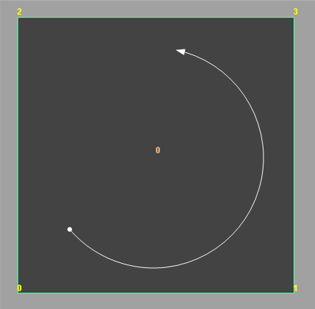
To examine the remapping that occurs, the hwPhongShader plug-in which uses the API to extract additional data buffers is used for an example. In this case, an instance of that shader is assigned to a shape with a single quad as shown above. The base face id and base vertex ids are shown, as well as the start vertex (dot) and winding order (curved arrow).
The render time buffers would look like this:
| Vertex Id (CCW winding) | Face id | Local UV |
|---|---|---|
| 0 | 0 | (0, 0) |
| 1 | 0 | (0, 1) |
| 3 | 0 | (1, 1) |
| 2 | 0 | (1, 0) |
Example 2: Smoothed Level 1 Quad - OpenSubdiv Catmull-Clark
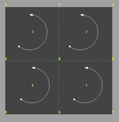
The topology shown above demonstrates one level of smoothing using OpenSubdiv. The start and winding order per sub-face and sub vertex is consistent for all levels with the base face.
The data buffers would appear as follows. Note that:
-
The Sub-Face Id column is added to show its correlation to the topology shown above, but is not provided as a separate vertex buffer.
-
Vertex ids 6 to 8 are not part of the base mesh.
Vertex ids 4, 5, 6, 7, 8 are vertices introduced as part of smoothing. The base mesh has vertices 0, 1, 2, 3. The dotted lines show where the subdivision occurred due to the smoothing operation.
-
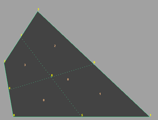
The local parameterization simply provides values to show the interpolation relative to the base vertices, and is not related to the actual placement of the vertex within the base face. For example, if vertex 8 was actually positioned close to vertex 0, the local UV value would still be (0.5,0.5), such as in this geometry:
| Vertex Id (CCW) | Face Id | Sub-Face Id | Local UV |
|---|---|---|---|
| 0 | 0 | 0 | (0, 0) |
| 5 | 0 | 0 | (0, 0.5) |
| 8 | 0 | 0 | (0.5, 0.5) |
| 4 | 0 | 0 | (0.5, 0) |
| 5 | 0 | 1 | (0, 0.5) |
| 1 | 0 | 1 | (0, 1) |
| 6 | 0 | 1 | (0.5, 1) |
| 8 | 0 | 1 | (0.5, 0.5) |
| 8 | 0 | 2 | (0.5, 0.5) |
| 6 | 0 | 2 | (0.5, 1) |
| 3 | 0 | 2 | (1, 1) |
| 7 | 0 | 2 | (1, 0.5) |
| 4 | 0 | 3 | (0.5, 0) |
| 8 | 0 | 3 | (0.5, 0.5) |
| 7 | 0 | 3 | (1, 0.5) |
| 2 | 0 | 3 | (1, 0) |
The provided index buffer can be used to access information per triangle.
As noted, the triangle split may not match the value specified for the quadSpit attribute on the polygonal shape. If we are given this triangulation:
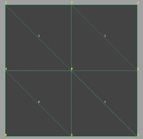
Then the index buffer would look something like this.
| Triangle number | Vertex Id |
|---|---|
| 0 | 0 |
| 0 | 5 |
| 0 | 4 |
| 1 | 4 |
| 1 | 5 |
| 1 | 8 |
| 2 | 5 |
| 2 | 1 |
| 2 | 8 |
| 3 | 8 |
| 3 | 1 |
| 3 | 6 |
| 4 | 8 |
| 4 | 6 |
| 4 | 7 |
| 5 | 7 |
| 5 | 6 |
| 5 | 3 |
| 6 | 4 |
| 6 | 8 |
| 6 | 2 |
| 7 | 2 |
| 7 | 8 |
| 7 | 7 |
Example 3: Smoothed Level 1 Quad – Legacy Catmull-Clark
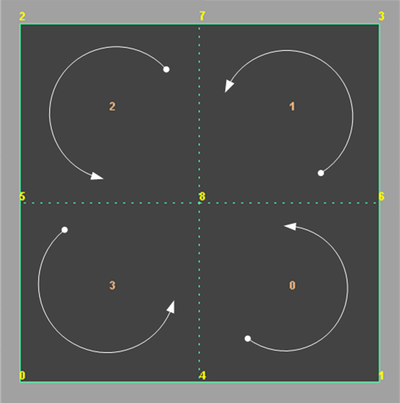
The topology above demonstrates one level of smoothing using the Legacy Catmull-Clark subdivision method. The shifting of the start of sub-faces and sub-vertices can be seen.
The data buffers would be as follows. As in Example 2, the Sub-Face Id column is added to show its correlation to the topology shown above, and is not provided as a buffer.
The shift in sub-face and sub-vertex start positions reflects what is shown in the diagram.
| Vertex Id (CCW) | Face Id | Sub-Face Id | Local UV |
|---|---|---|---|
| 4 | 0 | 0 | (0, 0.5) |
| 1 | 0 | 0 | (0, 1) |
| 6 | 0 | 0 | (0.5, 1) |
| 8 | 0 | 0 | (0.5, 0.5) |
| 6 | 0 | 1 | (0.5, 1) |
| 3 | 0 | 1 | (1, 1) |
| 7 | 0 | 1 | (1, 0.5) |
| 8 | 0 | 1 | (0.5, 0.5) |
| 7 | 0 | 2 | (1, 0.5) |
| 2 | 0 | 2 | (1, 0) |
| 5 | 0 | 2 | (0.5, 0) |
| 8 | 0 | 2 | (0.5, 0.5) |
| 5 | 0 | 3 | (0.5, 0) |
| 0 | 0 | 3 | (0, 0) |
| 4 | 0 | 3 | (0, 0.5) |
| 8 | 0 | 3 | (0.5, 0.5) |
Legacy Catmull-Clark has different indexing than OpenSubdiv Catmull-Clark, based on the fact that its start face and start vertices differ. Therefore, using the same example, the triangulation appears as follows:
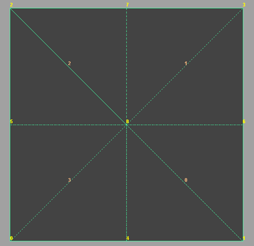
The indexing would be as follows:
| Triangle number | Vertex Id |
|---|---|
| 0 | 4 |
| 0 | 1 |
| 0 | 8 |
| 1 | 8 |
| 1 | 1 |
| 1 | 6 |
| 2 | 6 |
| 2 | 3 |
| 2 | 8 |
| 3 | 8 |
| 3 | 3 |
| 3 | 7 |
| 4 | 7 |
| 4 | 2 |
| 4 | 8 |
| 5 | 8 |
| 5 | 2 |
| 5 | 5 |
| 6 | 5 |
| 6 | 0 |
| 6 | 8 |
| 7 | 8 |
| 7 | 0 |
| 7 | 4 |
Example 4: Smoothed Level 2 Quad – Legacy Catmull-Clark
The following image shows a subdivision of level 2 using the Legacy Catmull-Clark method, and illustrates a repeat of the subdivision pattern.
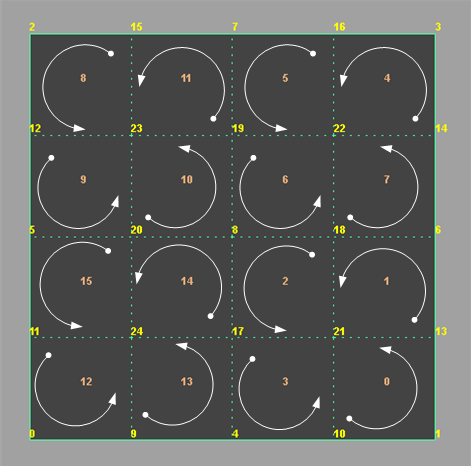
With the following data trace from the hwPhongShader plug-in:
| Vertex Id (CCW) | Face Id | Sub-Face Id | Local UV |
|---|---|---|---|
| 10 | 0 | 0 | (0, 0.75) |
| 1 | 0 | 0 | (0, 1) |
| 13 | 0 | 0 | (0.25, 1) |
| 21 | 0 | 0 | (0.25, 0.75) |
| 13 | 0 | 1 | (0.25, 1) |
| 6 | 0 | 1 | (0.5, 1) |
| 18 | 0 | 1 | (0.5, 0.75) |
| 21 | 0 | 1 | (0.25, 0.75) |
| 18 | 0 | 2 | (0.5, 0.75) |
| 8 | 0 | 2 | (0.5, 0.5) |
| 17 | 0 | 2 | (0.25, 0.5) |
| 21 | 0 | 2 | (0.25, 0.75) |
| 17 | 0 | 3 | (0.25, 0.5) |
| 4 | 0 | 3 | (0, 0.5) |
| 10 | 0 | 3 | (0, 0.75) |
| 21 | 0 | 3 | (0.25, 0.75) |
| 14 | 0 | 4 | (0.75, 1) |
| 3 | 0 | 4 | (1, 1) |
| 16 | 0 | 4 | (1, 0.75) |
| 22 | 0 | 4 | (0.75, 0.75) |
| 16 | 0 | 5 | (1, 0.75) |
| 7 | 0 | 5 | (1, 0.5) |
| 19 | 0 | 5 | (0.75, 0.5) |
| 22 | 0 | 5 | (0.75, 0.75) |
| 19 | 0 | 6 | (0.75, 0.5) |
| 8 | 0 | 6 | (0.5, 0.5) |
| 18 | 0 | 6 | (0.5, 0.75) |
| 22 | 0 | 6 | (0.75, 0.75) |
| 18 | 0 | 7 | (0.5, 0.75) |
| 6 | 0 | 7 | (0.5, 1) |
| 14 | 0 | 7 | (0.75, 1) |
| 22 | 0 | 7 | (0.75, 0.75) |
| 15 | 0 | 8 | (1, 0.25) |
| 2 | 0 | 8 | (1, 0) |
| 12 | 0 | 8 | (0.75, 0) |
| 23 | 0 | 8 | (0.75, 0.25) |
| 12 | 0 | 9 | (0.75, 0) |
| 5 | 0 | 9 | (0.5, 0) |
| 20 | 0 | 9 | (0.5, 0.25) |
| 23 | 0 | 9 | (0.75, 0.25) |
| 20 | 0 | 10 | (0.5, 0.25) |
| 8 | 0 | 10 | (0.5, 0.5) |
| 19 | 0 | 10 | (0.75, 0.5) |
| 23 | 0 | 10 | (0.75, 0.25) |
| 19 | 0 | 11 | (0.75, 0.5) |
| 7 | 0 | 11 | (1, 0.5) |
| 15 | 0 | 11 | (1, 0.25) |
| 23 | 0 | 11 | (0.75, 0.25) |
| 11 | 0 | 12 | (0.25, 0) |
| 0 | 0 | 12 | (0, 0) |
| 9 | 0 | 12 | (0, 0.25) |
| 24 | 0 | 12 | (0.25, 0.25) |
| 9 | 0 | 13 | (0, 0.25) |
| 4 | 0 | 13 | (0, 0.5) |
| 17 | 0 | 13 | (0.25, 0.5) |
| 24 | 0 | 13 | (0.25, 0.25) |
| 17 | 0 | 14 | (0.25, 0.5) |
| 8 | 0 | 14 | (0.5, 0.5) |
| 20 | 0 | 14 | (0.5, 0.25) |
| 24 | 0 | 14 | (0.25, 0.25) |
| 20 | 0 | 15 | (0.5, 0.25) |
| 5 | 0 | 15 | (0.5, 0) |
| 11 | 0 | 15 | (0.25, 0) |
| 24 | 0 | 15 | (0.25, 0.25) |
