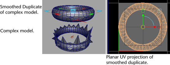
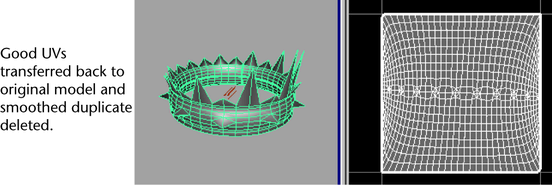
To transfer UV, color per vertex (CPV), and vertex position information between meshes that have differing topologies (that is, the number, arrangement, and connectivity of vertices on each mesh is not identical) use the Transfer Attributes feature.
Transfer Attributes transfers vertex data by sampling the vertex information on the source mesh and then transferring the information to the specified target mesh, based on a comparison that is spatially based. The target mesh gets modified as a result.
Transferring vertex attributes using Transfer Attributes is useful in the following situations:
- Transfer a finished UV layout, including multiple UV sets, from one surface mesh to another mesh that has no existing UVs.
- Transfer a UV layout from a high resolution model to a low resolution version.


- Transfer color per vertex (CPV) data, including multiple color sets, from a high resolution model to a low resolution version.
- Modify the vertex positions on a low resolution surface mesh to match the positions on a high resolution version.
- Mirror vertex information from one half of a surface mesh to another half. For example, you can ensure symmetry of UV, vertex, and color information on one mesh by sampling the attribute information from one half of the mesh and transferring the data to its opposite half.
Note:
You can set the Transfer Attributes feature to transfer the UV sets, CPV color sets, and vertex position data either separately or all at once depending on your requirements.
While the source and target meshes can vary widely in their topology, the default transfer settings require that the objects be positioned in identical locations spatially because of the nature of the sampling and transfer process that occurs.
You can also use Transfer Attributes to flip the orientation of the UV shells as they appear in the UV Texture Editor. This streamlines your UV layout and texturing workflow.
To transfer attributes between separate meshes
- In the scene view, move the source and target meshes so they are positioned and oriented as you want for the attribute transfer. Ensure that the source mesh and then the target mesh are selected in that order.
Note: The order of selection is important. The last object selected is always considered the target for the transfer operation.
You must select the source mesh in object mode, you can select the target mesh either in object mode or by selecting the individual vertices in the region to be modified on the target mesh.
If you have difficulty selecting either the source or target meshes in the scene view, change the display of the meshes to wireframe mode or select them using the Outliner ().
- Select
. In the
Transfer Attributes Options window, specify the
Attributes to Transfer as follows:
- Set Vertex position to On if you want to transfer the vertex positions on the source mesh and have the vertices on the target mesh modified to match. The default setting is Off.
- Set UV sets to All if you want all UVs from the source mesh sampled and transferred to the target mesh. When multiple UV sets exist, the All setting ensures they are all sampled and then transferred to the target mesh. If the source mesh has more than one UV set, you can selectively transfer the currently active UV set by selecting the Current option. The default setting is All.
- Set Color sets to All if you want all of the CPV data for the source mesh sampled and transferred to the target mesh. When multiple color sets exist, the All setting ensures they are sampled and then transferred to the target mesh. If the source mesh has more than one CPV set you can selectively transfer the currently active color set by selecting the Current setting. The default setting is All.
- Specify how you want the sampling to occur by setting the
Sample space setting as follows:
- Use the World setting to sample in world space. It should be used for the majority of your attribute transfer operations. This is the default setting.
- Use the Local setting when the objects are the same size and shape, but may have been translated, rotated or scaled in the scene (for example, you have two chairs in different locations). The Local setting is used when you want to compare the source and target side by side.
- Use the
UV setting to sample attributes in UV space when no useful spatial correlation exists between the source and target meshes. For example, when the meshes are of radically different proportions or have been constructed at different scales but the meshes share a common mapping in UV space. For example, models of a giant and a dwarf can correlate based on their UV texture coordinates if the UV mapping for their faces is in the same position in UV texture space.
Note: Using UV setting to determine how the transfer of attributes will occur is very different from physically transferring UV data between models. Transferring of UV attributes is usually done using the World or Local space settings.
- Use the Component setting to transfer attributes directly from one component to another via their component IDs. To use this setting, both objects must have the same number of vertices, faces, and edges, and the relationship between these components must be the same on both objects. For example, use this setting if you want to transfer a UV texture map from one head to a stretched version of the same head.
- Use the Topology setting to transfer attributes directly from one component to another when the objects’ topologies are identical, but their component IDs are not. For example, some options in Maya may rearrange the vertex order on a model. This option allows you to transfer a texture map from the original mesh by their matching topologies, rather than their non-matching vertex order.
- Set the remaining options based on other specific requirements:
- Set the Mirroring option when you want the attribute transfer to occur across a defined axis (X, Y, Z). Ensure that you have selected the vertices along the mirror border. You must set a mirroring axis when the source sampling and target transfer occurs on the same mesh. The default setting is Off.
- Set the Flip UVs option when you are sampling UVs and want the transferred UV shells to be flipped along the U or V axes as they appear in the UV Texture Editor. This is useful when you are mirroring UVs on the same surface mesh. The default setting is Off.
- Set Color borders to Preserve if you want the hard color edges in the source mesh maintained when the CPV data is transferred to the target mesh. Otherwise, if the surface topologies differ widely, you may set the Color borders option to Ignore. The default setting is Preserve.
- Click Transfer to transfer the attributes and close the options window or click Apply to transfer the attributes and keep the window.
To mirror vertex attributes on the same surface mesh
- In the scene view, select the components on the surface mesh (that is, faces, vertices, or edges) that you want to have modified by the
Transfer Attribute feature.
The Transfer Attributes feature samples the surface about the specified mirroring axis and assigns new values to the selected components. All unselected components retain their original attribute values.
- Select .
- Depending on your workflow, set the
Transfer Attributes options as follows:
- Specify the attributes you want transferred (Vertex Position, UV Sets, Color Sets)
- Specify the axis you want the attributes mirrored along. For example, if you want the attributes mirrored along the X axis based on what you have selected, set the Mirroring axis to X.
- Click Transfer to transfer the attributes and close the options window, or click Apply to transfer the attributes and keep the window open.