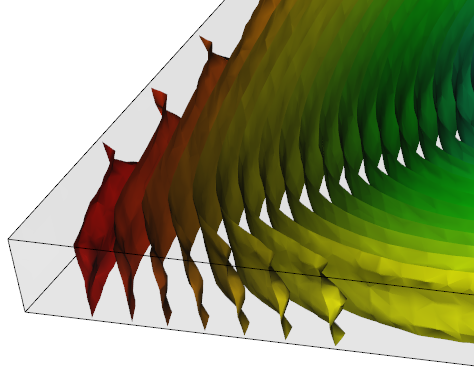
The Deflection, orientation effects result shows the final part warpage due to the material orientation throughout the part. If the material is fiber filled, this corresponds to the fiber orientation in the part.
- Against an anchor plane where three points are specified on the part that define a plane. The deflection of the warped part in relation to this plane is measured.
- The deformed geometry is measured against a Best Fit plane. The plane is defined in such a way that the total displacement of Reference points is as small as possible. As many reference points as required can be specified.
A Dual Domain part shows surface contours only but warpage through the thickness can often be inferred.
Using this result
Examine the extent of the deflection of the part and ensure the result is within tolerance.Small deflections can be magnified using the Scale factor setting on the Deflection tab of the Plot Properties dialog.
Deflection results can be animated. the animation illustrates the change in shape of the part from the original part shape to the final deflected geometry.
Things to look for
Variation in the magnitude of the shrinkage in directions parallel and perpendicular to the material orientation causes orientation deflections. This is similar to differential shrinkage. Methods to influence this deflection apart from selecting another material are outlined.
- Change the molding conditions
- Change gate location
- Change part thickness