The Deflection, differential cooling result shows the final part warpage due to uneven cooling.
Note: For this result to be available for a 3D part, select Disable aggregation for 3D warp analysis from the Advanced tab of the Analysis Wizard.
This result is calculated one of two ways.
- Against an anchor plane where three points are specified on the part that define a plane. The deflection of the warped part in relation to this plane is measured.
- The deformed geometry is measured against a Best Fit plane. The plane is defined in such a way that the total displacement of Reference points is as small as possible. As many reference points as required can be specified.
Tip: To view the warpage through the thickness of a 3D part, alter the result display to Contour (right click the result name in the Study Tasks pane and select ).
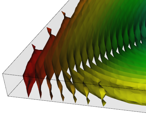
A Dual Domain part shows surface contours only but warpage through the thickness can often be inferred.
Using this result
Examine the extent of the deflection of the part and ensure the result is within tolerance.
Small deflections can be magnified using the Scale factor setting on the Deflection tab of the Plot Properties dialog.
Deflection results can be animated. the animation illustrates the change in shape of the part from the original part shape to the final deflected geometry.
Things to look for
The following points should be considered when minimizing warpage.
- The temperature difference between the top and bottom side of an area should be within an acceptable range.
- Eliminate hot spots to achieve more even cooling.
- Adjust the spacing between cooling channels and the mold cavity.
- Adjust the spacing between adjacent cooling channels.