The meeting of flow fronts can cause weak points within the part. The Weld surface movement (3D) result tracks the formation and movement of these surfaces through the Fill, Pack and Cool cycle.
After the surfaces are initially formed, they might move and end up in locations removed from their initial formation. Factors such as flow front temperature, material transition temperature, shear rate and mold temperature will influence the mobility of these surfaces. This animated result shows this movement.
An example of how weld surfaces can move is shown in the following series of screen shots.
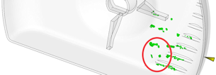
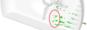
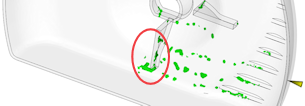
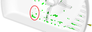
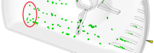

If the part had a surface blemish in the area highlighted in the last image, it might be as a result of the weld surface that was formed in the first image.
To properly investigate a weld surface, one or more of the following may be required.
- A finer mesh
- Shorter solver time steps
- More frequent results output
The analysis will have to be re-run for any change to take effect.
- To generate shorter solver time steps, decrease the Maximum %volume to fill per time step, (). The default is 4%.
- To get more frequent results output select Write at constant intervals or Write at specified times from the Intermediate results panel and edit as required
Using this result
When looking at the strength of a part, weld surfaces are a source of potential weakness. The Weld surface movement (3D) traces the weld surface throughout the filling, packing and cooling phase and not just the initial surface formation.
A weld surface that does not move is a source of potential structural weakness, while surfaces that move could account for surface blemishes as material from the weld surface might be deposited on the surface of the part.
If the material is fiber filled, the meeting of the flow surfaces might also inhibit the localized orientation of these fibers in the finished part.
Things to look for
Weld surfaces that are in critical sections of the part, or are on visible surfaces may need to be moved by techniques such as changing gate locations or by strategically altering part thickness.