This topic provides examples of an insert that is in poor contact with the surrounding mold, an insert that is in good contact with the mold, and a stepped insert.
Inserts in poor contact with the mold
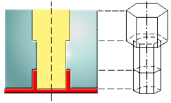
This modeling assumes there is poor contact between the insert and the rest of mold material due to clearance for ease of mold assembly.
This picture illustrates how inserts in poor contact with the mold material are modeled. The surface in contact with the air gap is assigned a very low interface conductance value. The insert is made from three surfaces, each with eight sides, creating three independent closed volumes.
Inserts in good contact with the mold
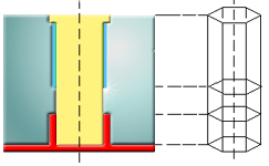
This modeling assumes there is a good contact between insert and rest of the mold material.
Alternatively, create a single insert of the required length with internal points or boundaries.
Stepped inserts
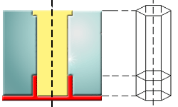
Model stepped inserts by creating one insert to represent the small end and a second to represent the larger end. The end face of the larger insert must have an internal boundary the same size as the smaller insert to ensure connectivity between the inserts.