Before you can run an analysis, you must have a meshed model. The mesh is a web that consists of elements, with each element containing a node at every corner. The mesh represents the part shape and provides the basis for the analysis, where molding properties are calculated at every node.
The selected mesh type, or analysis technology, determines which molding processes and which analysis sequences are available for selection.
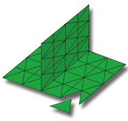
Midplane analysis technology
A Midplane mesh provides the basis for the analysis. This mesh consists of three-node, triangular elements that form a one-dimensional representation of the part shape through its center, or midplane. The thickness of the part is represented by a thickness attribute applied to the mesh elements.
- the part is thin-walled throughout.
- The analysis you want is available only in Midplane.
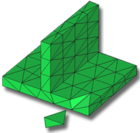
Dual Domain analysis technology
A surface mesh provides the basis for the analysis. This mesh consists of three-node, triangular elements that form a one-dimensional representation on each surface of the part. The mesh elements are matched across opposing faces. The thickness of the part is determined by the distance between the opposing faces.
The model could be visualized as a hollow body covered with a surface shell.
- The part is generally thin walled with few thick areas. The minimum length and width of any local region should be greater than four times the local thickness. A more conservative estimate of ten times the thickness ensures more accurate results.
- The analysis that you want to run produces results through the thickness of the part, for example, temperature, flow front, and shear rate.
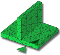
3D analysis technology
A volume mesh provides the basis for the analysis. This mesh consists of solid, four-node, tetrahedral (tetra) elements; each tetra has four triangular faces and six sides.
- The part has many thick sections, corners, features or walls. 3D analysis technology is recommended for parts where the length and width of a section is less than four times the local thickness.
- You want to accurately model non-laminar flow around corners and features.