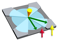
Surfaces with thicknesses designed to direct the flow front either by attracting the flow with leaders or by deflecting the flow with deflectors.
As indicated by the yellow arrow in the following diagram, flow leaders are thicker parts of the cavity, which attract the flow. As indicated by the red arrow in the following diagram, deflectors are thinner parts of the cavity which constrict the flow and slow it down.

- The thickness change in a flow leader or flow deflector should not be greater than 25% of the wall thickness.
- There should be a gradual change in thickness between the flow leader/deflector and the surrounding part. The diagram above is stepped, but this is for illustration purposes.
- Cooling times for the part might be lengthened if the flow leader is the thickest section of the part.
- Strength of the finished part might be compromised if a flow deflector is used in a critical section of the part.
| Advantages | Disadvantages | |
|---|---|---|
| Flow leaders |
|
|
| Flow deflectors |
|
|