- Right-click on
Loads under
Subcase 1 and choose
New.
- Enter
NLssht Loads
under
Name.
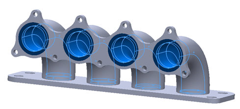
- Select
Heat Flux from the
Type drop-down menu and select the inside surfaces for Flange 2 and all four tubes that make up the hole. The surfaces are highlighted in blue in the image below.
- Under
Load Definition enter
0.035 for
Heat Flux and make sure that
Subcase 1 is highlighted so that the load is automatically added to
Subcase 1.
- Click
 New button to define another load.
- Enter
Convection
under
Name.
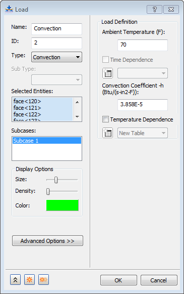
- Select
Convection from the
Type drop-down menu.
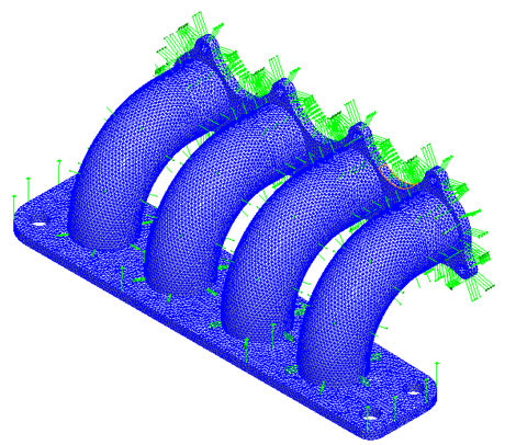
- Select one of the sides that make up the thickness of Flange 2 and select all the tangent surfaces to the surfaces already selected. Continue to select the surfaces of Flange 1 and 2 facing the tubes, as well as the exterior surfaces of the tubes. The surfaces that should be selected are shown below.

- Enter a
Convection Coefficient value of
3.858E-5 BTU / (sec·in2·°F) and an
Ambient Temperature of
70 °F.
- Make sure that
Subcase 1 is highlighted so that the load is automatically added to
Subcase 1.
- Click
OK to complete the loads definition.
- Click
New button to define another load.
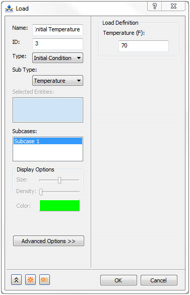
- When the
Load dialog appears again, enter
Initial Temperature
in the
Name field and select
Initial Condition from the
Type drop-down menu.
Temperature should appear in the
Sub Type drop-down. Then enter
70 under
Temperature in the Load Definition section. This defines the initial temperature of the body and you are assuming that it is the temperature of the ambient air surrounding it.
- Select
Subcase 1 so that this load is automatically added to
Subcase 1.
- Click
OK.